
Cam Swaps Made Easy
This article was originally published in the October-November 1997 issue of Cycle World’s Big Twin magazine.
In the grand scheme of H-D Big Twin engine hop-ups, changing the cam is among the first three or four most logical steps. Once you’ve opened up the inlet side with freer-flowing air filter and carburetor, and uncorked the exhaust system, swapping out the standard cam is the aural next move.
Replacing the cam in a Big Twin is easier an on a lot of other engines; still, there are ads of tricks and techniques the experts use that can make the difference between a tiresome, difficult job and one that is exhilarating and rewarding.
This is, however, not a job for the first-timer. You will delve far enough into the engine to wreak some serious damage if you don’t know what you’re doing. Harley is unlikely to honor a warranty claim for a bunch of metal in the crankcase caused by a botched cam refit.
For the initiated, a cam swap is straight-forward, even enjoyable. The cam’s location inside the right-outboard engine case makes most of the work undemanding on the human body; you can do the whole job within reach of your cooler.
Start by hoisting the bike on a lift. If you don’t have one, make sure you have a roll-around chair or, at the very least, a comfy milk crate. At some point, you will need to shift the gearbox into fifth and rotate the rear wheel to help index the cam; a pair of tiedowns and a carefully positioned floor jack should do the trick. Now remove the airbox and filter, and pull both sparkplugs.
Have all of the requisite parts ready—the new cam, a new timing-cover gasket and a replacement inner cam bearing (more on that later). You’ll need two special blind pop-rivets (H-D part No. 8699) when you reinstall the timing-cover end plate; do not use regular pop-rivets, which can allow the rivet shank to fall inside the cover. As for special tools, you should have a set of Crane’s nifty lifter retractors, a puller for the inboard needle bearing, clothespins (to keep the pushrod shrouds out of your way), and ignition-timing equipment. You should also have a service manual at the ready; it’s foolish to try anything as involved as a cam swap without one.
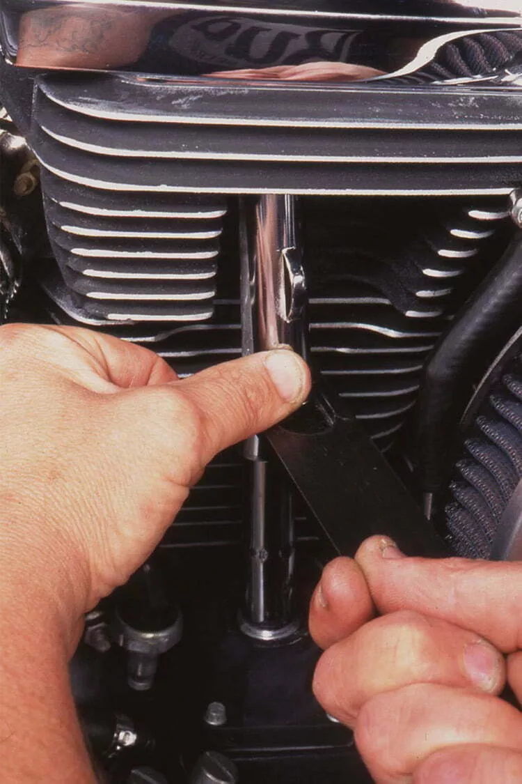
Figure 1
Jim Boyle
Let’s jump ahead momentarily. if you intend to replace the stock steel pushrods with lighter, adjustable rods, you can omit several of the following steps. Why? Because instead of dismantling the rocker box to free the pushrods, you’re going to chop them in half with bolt cutters. Their replacements will be one of the several aftermarket sets available that have extra-long adjusting threads to allow reassembly without disturbing the rocker boxes.
If you intend to retain the stock push-rods—which work fine for mildly tuned engines—you must remove the fuel tank to gain access to the rocker boxes. Make sure you account for all of the gasket pieces and the flexible seals under the bolts that secure the top rocker cover. Once there, you must remove the rocker-arm shafts to relieve the valve-train pressure. Keep all of the rocker shafts and arms in order so they can go back from whence they came. Then remove the lower rocker-box section. Unclip the push-rod-cover retainers and set them aside (see Figure 1); keep them organized in the order they were in on the bike.
Now either lift the pushrods out of the lifter-block cavity or mercilessly hack them in half. (If opting for the latter method, be sure you don’t get any metal into the lifter blocks or upper lifter faces.) Extricate the pushrod shrouds as you remove the pushrods.
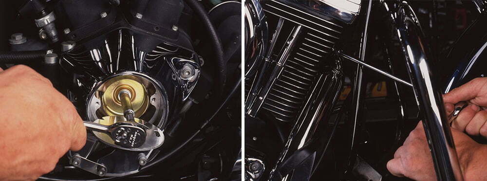
Figure 2 (left) and figure 3 (right)
Jim Boyle
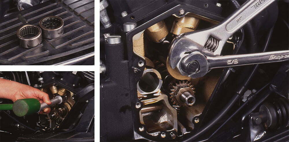
Next, drill out the two blind rivets that secure the timing-cover end plate. This exposes a cover plate, which you will also re-move, and the backing plate for the ignition sensor. Remove it and the ignition rotor (see Figure 2). Before separating the gear cover from the crankcase, you may have to loosen (see Figure 3) and slightly relocate the front exhaust pipe. Touring models will need to have the right floor-board temporarily relocated to clear the area.
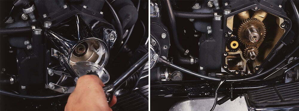
Figure 4 (left) and figure 5 (right)
Jim Boyle
Remove the six Allen-head bolts holding the gearcase (see Figure 4); there are three different bolt lengths, so remember which goes where. You may need to tap the case lightly with a rubber mallet to break it loose, but don’t even think of prying the faces apart with a screwdriver. When you get the cover off, the cam cavity will have a few ounces of oil in it but should not be flooded (see Figure 5); if it is, carefully check the breather system for obstruction and for the proper indexing of the breather gear.
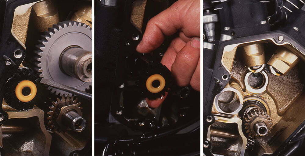
Figure 6 (left), figure 7 (center) and figure 8 (right)
Jim Boyle
With the transmission in top gear, rotate the rear wheel to orient the cam-drive mechanism so the timing marks (see Figure 6) on the cam, pinion drive and breather gear align. (If they don’t, you’ll then know why the bike has been running so poorly, eh?) Now remove the breather assembly (see Figure 7), then reach in and move the lifters up out of the way (many mechanics have nifty magnets embedded in fork-like tools that hold the lifters up in their bores). Carefully pull the cam out of the inner needle bearing and free of the case. Take a moment to inspect the inside of the gearcase (see Figure 8) for contaminants and evidence of metal-to-metal contact. Then inspect the old cam’s lobes for wear or signs of damage; if you find any of either, carefully inspect the oilers on the lifters, which are likely to exhibit a similar condition.
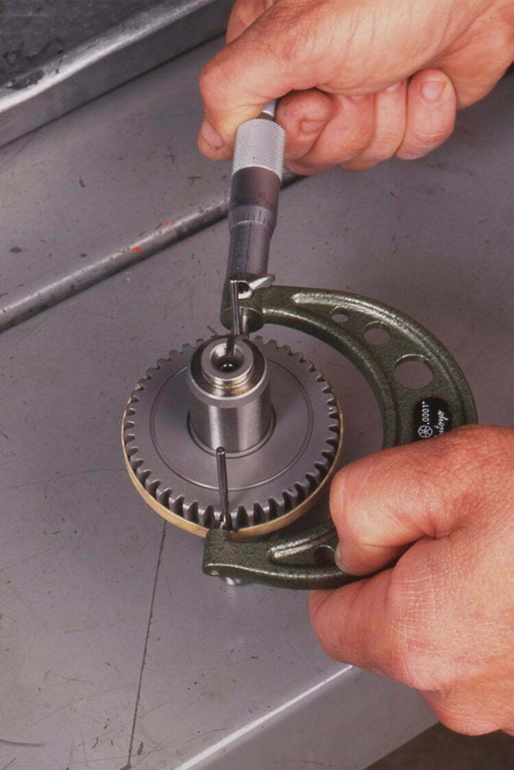
Figure 9
Jim Boyle
Here’s where the job gets a bit technical: Harley-Davidson manufactures Big Twin engines with seven possible combinations of cam-gear and pinion-gear diameters, and the gears are matched at the factory for optimum it. Each cam and pinion set is color-coded so you can tell at a glance which size they are, and the increments are necessarily tiny. For example, a red cam gear’s diameter—when measured across a pair of special, 0.108-inch Pins (available from the cam manufacturers) aligned in the gear’s teeth (see Figure 9)—is between 2.7487 inches and 2.7491 inches; that’s an allowable variation of just four-ten-thousandths of an inch.
All of the aftermarket cam manufacturers build their cams to the middle of the range, under the red color code. If your engine is fitted with any other color-coded cams, you have a couple of options. Most mechanics will tell you that for engines fitted with stock cam gears one size on either side of red—that is, with blue or yellow codes—you can safely use the aftermarket cam without alteration. If this results in the cam gear being slightly loose, you’ll likely have some gear noise that sounds like lifter clatter. If it’s a bit tight, you’ll hear some gear whine. Neither condition should be objectionably loud. For engines fitted by the factory with any of the remaining four color codes, you have two basic options: One is to have a competent machine shop press the gear off your stock cam and onto the aftermarket unit; the other option is to have the aftermarket cam manufacturer do the same thing. All of them will do this work, usually at no extra charge.
Clockwise from top right: Figure 10, figure 11, figure 12
Jim Boyle
At this point, the next step is to replace the stock inner cam bearing with a replacement Timken model that’s far more robust than the original (see Figure 10). Removal (see Figure 11) and replacement (see Figure 12) of the bearing are straightforward tasks—if you have the proper tools. But if you don’t have them, don’t attempt the job yourself; have it done by a dealer or shop in your area that has the equipment and knows how to use it. Either way, however, do replace the stock bearing; it’s not up to handling the increased loads induced by a higher-lift cam.
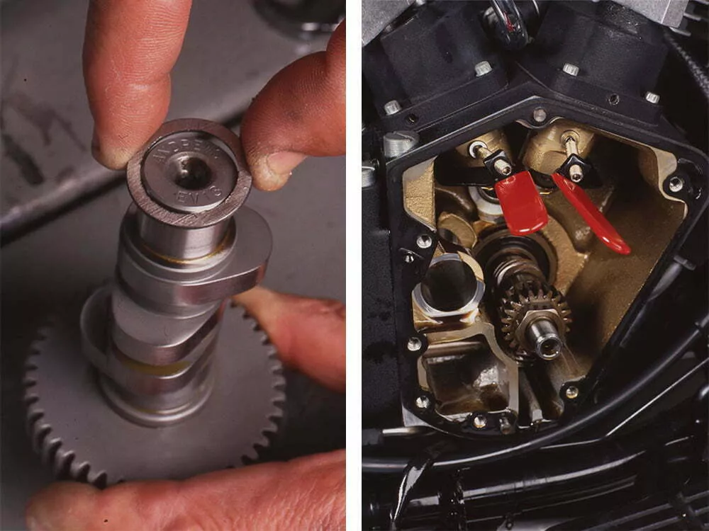
Figure 14 (left) and figure 15 (right)
Jim Boyle
Pre-’88 Big Twins came with a thin spacing washer and a thick thrust washer on the in-board end of the cam; later models use only the thrust washer. But all aftermarket cams require both washers (see Figure 13). If your engine came with both, install them; if it didn’t, you’ll have to buy a thin one from your dealer. Next, push the lifters up into their bores and use the lifter clamps (see Figure 14) to hold them out of the way. Now, carefully work the cam into position, aligning the timing marks (see Figure 15) on the cam gear with those on the drive gear.
Before reinstalling anything else, take a moment and turn the rear wheel to determine that there’s no contact between the innermost lobe of the new cam and the slight bulge that’s cast into the crankcase just above needle-bearing boss; some high-lift cams require minor machining here to provide adequate clearance between the case and the lobe. Once again, if you have both the tools and the knowledge needed to do this job, proceed; otherwise, take the work to a qualified bike-repair shop or machinist.
Release the lifter clamps and make sure the rollers contact the center of the lobes. Next, reinstall the breather assembly, being careful to index the gear; then reinstall the cam-case cover, using a new gasket. Replace the bolts and torque them to 90 to 120 inch-pounds (or as specified in the shop manual if the figure is different). If you’ve decided to stay with the stock pushrods—which are perfectly adequate for most aftermarket cams—you now can drop the pushrods back in place (mind the color coding so you get the right rods back into the right holes) and reassemble the rocker shafts and boxes, using new gaskets.
Figure 16
Jim Boyle
You will need to ensure that for each rocker shaft you reassemble, the cam is on the base circle for that valve. An easy way to determine this is to pick one of the intakes, for example, and turn the engine until one of the intake lifters is squarely on the tip of its cam lobe; at that point, the other intake will be on the base circle. The same rule of thumb applies for the exhausts.
If you’ve made the switch to adjustable pushrods, there’s another step—particularly if you’ve decided to cut the stock pushrods rather than disassemble the rocker boxes. As mentioned above, pick one of the valves and ensure that its lifter is riding on the base circle. Install that valve’s pushrod and use its adjuster to tighten it until the slack is out (see Figure 16), then continue to tighten it by the number of turns specified by the pushrod maker—usually two to three turns. This preloads the lifter to ensure that it will work in the center of its range of travel. Allow 10 to 20 minutes for the lifter to bleed down—the pushrod will turn freely when the bleeding is complete—and then continue to the other valves. Reassemble the timing components, air filter, exhaust pipe, sparkplugs and anything else you had to move out of the way. Finally, perform the recommended ignition-timing routine as spelled out in the service manual.
That’s it. Listen carefully for strange noises when you restart the bike. And, of course, enjoy the ride as you revel in your engine’s newfound performance.

")


