
The First Direct Drive Starter
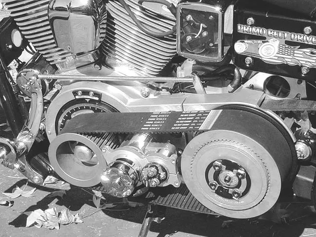
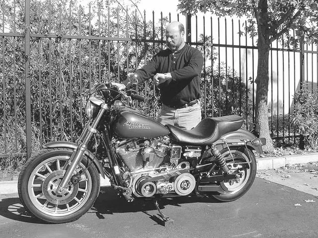
1. Here is the prototype Direct Drive Starting System mounted on Compu-Fire’s Harley-Davidson Dyna test bike, fitted with a 95ci S&S; engine, with 220 pounds of cylinder cranking pressure.
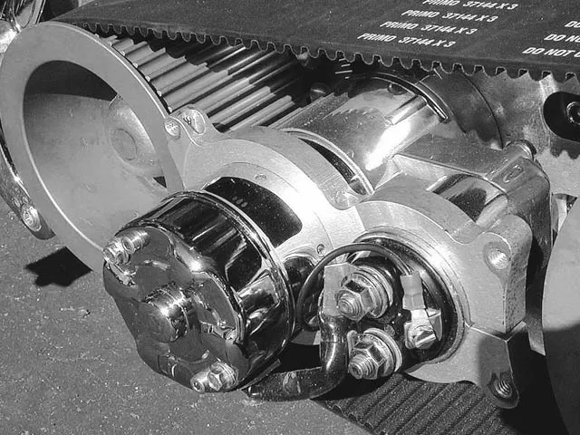
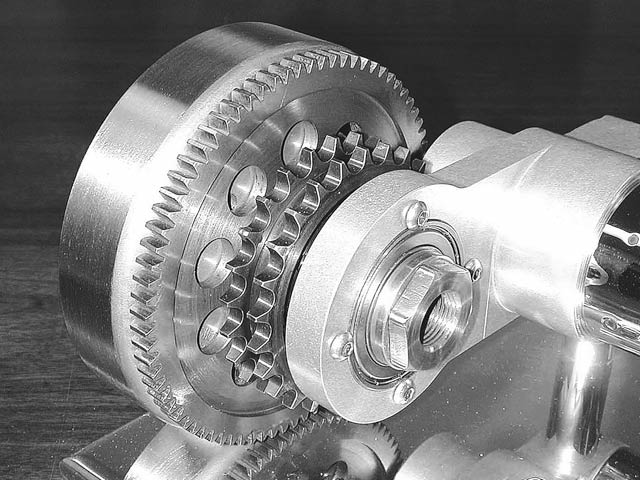
2. Here’s another view of the cranking motor and its close proximity to the alternator rotor. The ring gear now drives the crankshaft directly. The contoured aluminum bracket (arrow) is for mounting the belt cover.
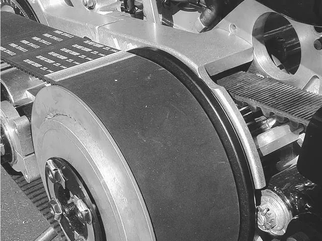
3. The Rivera/Primo 3-inch beltdrive is precisely machined for the Direct Drive Starter System. The standard starter motormount was removed from the inner motor plate.
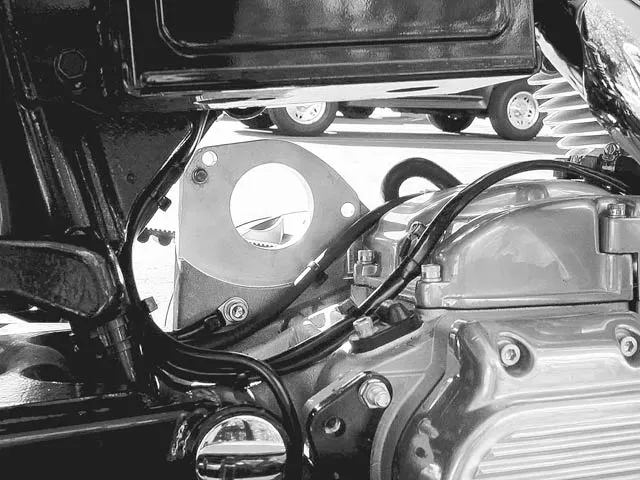
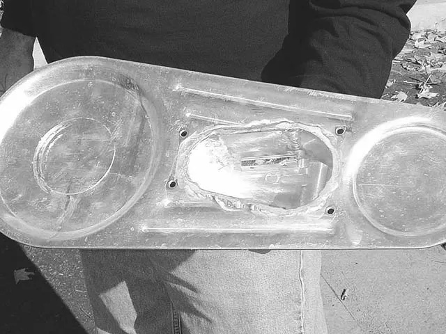
4. A look under the battery tray on the Dyna shows how much room is now available once the cranking motor has been relocated to the primary plate.
5. Part of the demonstration had Steve Seeman from the R&D; department cranking the engine for a full 15 seconds (the gas was turned off), then letting the bike set for one minute, then cranking the engine for another 15 seconds straight. Steve repeated this two more times, then asked us to touch the cranking motor. We did, and it was barely warm to the touch, not hot like a conventional motor.
6. Since the unit we were checking out was a working prototype, the outer beltdrive cover was modified to encase the end of the cranking motor. Future developments of the D2S will feature more compact cranking motors.
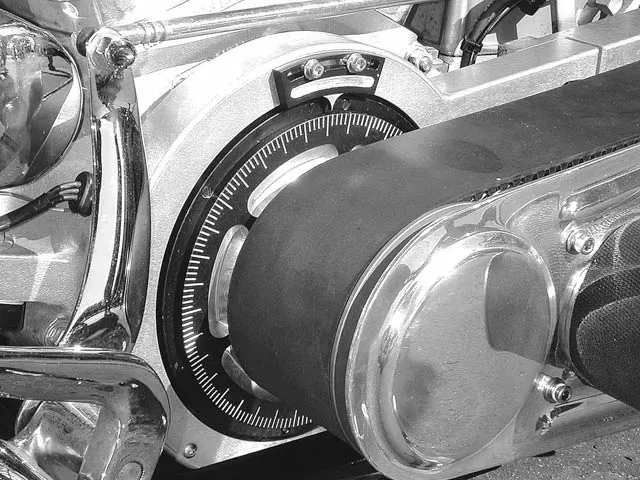
7. The prototype unit was fitted with a degree wheel on the outside of the alternator rotor, (notice how the enlarged motor plate covers the timing hole in the engine’s crankcases). The timing pointer above the degree wheel is adjustable to obtain an accurate top-dead center for timing the engine’s ignition system.
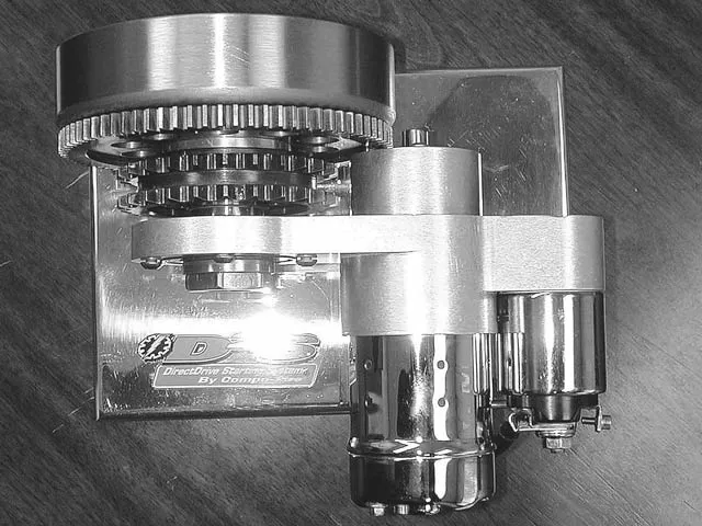
8. Compu-fire also had a bench-top display of the D2S system for chaindrive primaries so we could spin it around and check it out from all angles. Notice the close relationship of the starter ring gear to the pinion gear (arrow), very much like an automotive starter setup.
9. Another view of the bench model shows how the ring gear and alternator rotor have holes machined in their surfaces to lighten the weight of the rotating mass and to improve stator cooling.
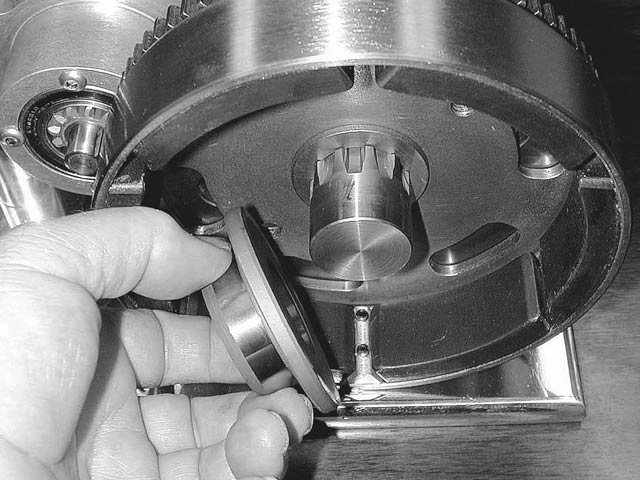
10. To provide additional support to the rotor shell, a new sprocket shaft seal spacer, with an increased diameter and thicker washer, was designed and is part of the new D2S system.
In 1964, the Harley-Davidson Motor Company smacked an electric starter on its big twins and launched a completely new world for motorcycle riders. The first starter motors, which were really cranking motors, were adaptations from the automotive industry. Not much has changed since 1964.
True, there has been a selection of different cranking motors installed on Harley-Davidson big twins since the first one appeared on Panheads, but the basic location of the cranking motor (above the transmission, bolted to the inner primary cover) has remained the same. Compu-fire Performance Products in Pomona, California, re-thought and redesigned the entire cranking motor system for big twins by placing the cranking motor in a new central location. Compu-fire mounted the starter motor to the inner primary plate, between the engine’s output sprocket shaft and the clutch drum (which is mounted to the transmission’s main shaft). This unique and innovative cranking motor configuration is available and works in conjunction with a Rivera/Primo beltdrive.
Cranking motors turn electrical energy, which is stored in the battery, into mechanical energy by powering the cranking motor, which spins the engine. Most batteries are designed to provide maximum cranking battery power to the cranking motor at 8 volts. The amount of cranking amps varies from battery to battery, depending on its construction. The amount of amperes sent to the cranking motor dictates the amount of rpm’s the cranking motor’s armature turns. This is the torque value of the cranking motor. The cranking motor is not large enough to turn the engine over by itself, it needs additional help. That assistance comes in the form of a gear reduction which is bolted to the primary side of the starter motor and drives the ring gear on the clutch basket.
When the starter button is depressed, electricity flows from the battery to the cranking motor, kicking-off a chain of events, which starts the engine.
Remember, the cranking motors used on big twins originated from the automotive world, where they have the advantage of much greater battery amperes and higher-torque motors. The automotive industry arrived at what it considered the optimum combination for cranking the ring gear, mounted to the engine’s flywheel: A ratio of 60:1 (eight cylinders or two, it doesn’t matter). Most non Compu-fire cranking motors currently available operate using a 21.6:1 ratio. The Compu-fire Gen III starter raises this ratio to 44:1 when used with the 10-84 pinion/ring gear set. The new engine-driven D2S further raises the ratio to 60:1. These ratios are dictated by the number of teeth on the armature gear combined with the number of teeth on the ring gear, mounted to the clutch basket. It can use this optimum ratio because it can match a ring gear bolted to the alternator rotor to a specific-sized pinion gear on the cranking motor. With the optimum ratio employed in this manner, battery life is extended. There are no worries about drawing too much current from the battery. Any ignition will fire and there’s ample current to power any fuel-injection system.
The D2S is the answer for large-displacement engines, with high cylinder cranking pressures. They may be tough to start using conventional systems, but the power of the D2S will even kick-off the larger-displacement engines under adverse conditions of cold weather or low battery charge. The Direct Drive Starter System from Compu-fire will be available by the time you read this article.


")

