
Sweet Tracker | ISR Controls and Barnett Cables
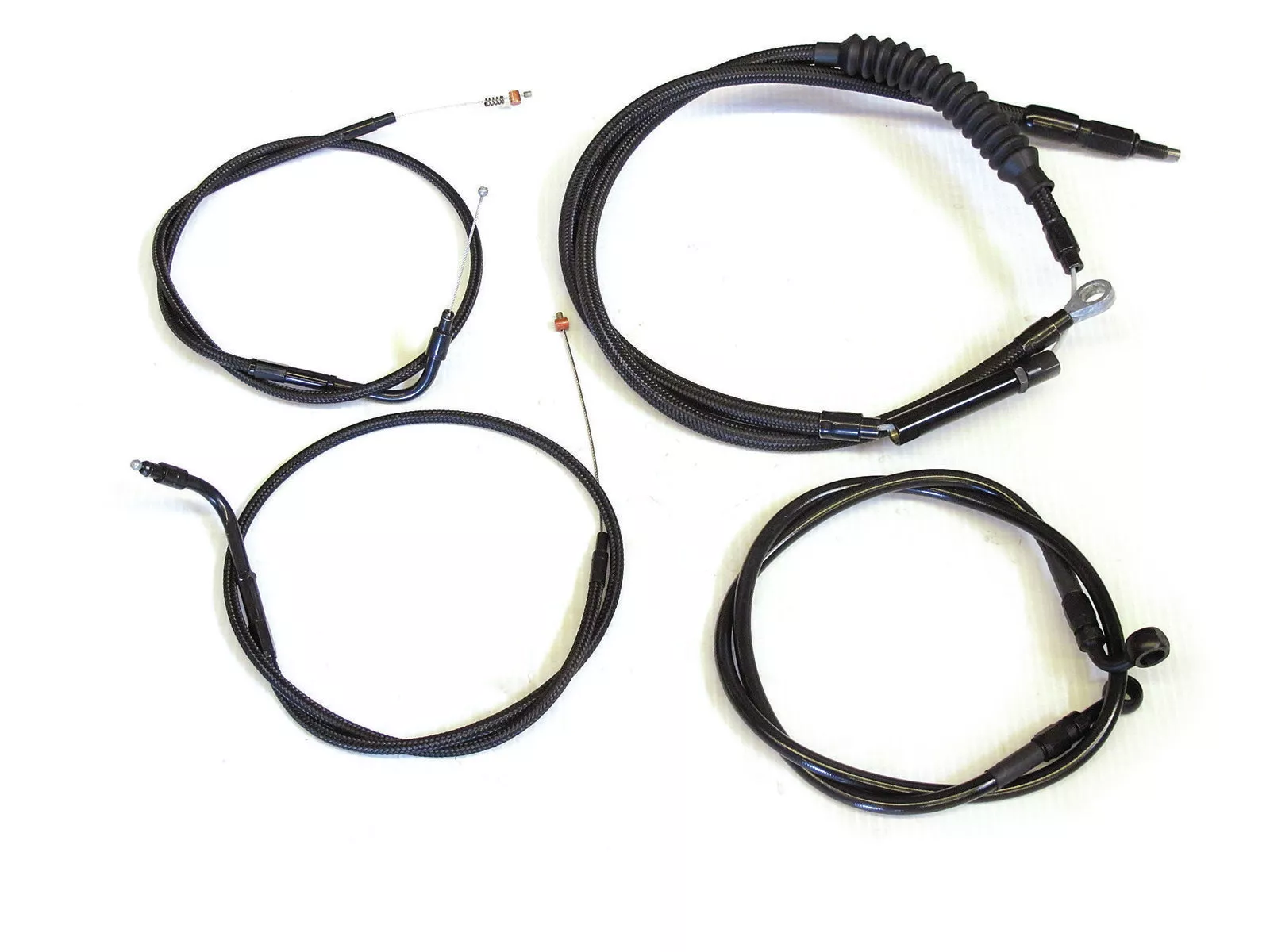
The ISR Hand Controls and Barnett cables are the perfect complement to the Sweet Tracker. Made from billet aluminum then anodized gold to match the black and gold theme of the bike, the ISRs combine a racey aesthetic with exceptional quality. To allow the controls to work, Barnett’s new matte black braided throttle/idle cables (A), and clutch cable (B) are top quality and also provide a racey look due to their no-sheen appearance. Lastly, I needed something to transfer the front brake fluid, so I grabbed a black-on-black 34-inch brake line (C) with a 90-degree bend at the caliper with no bend at the master cylinder from the local Harley dealership.
The ISR Hand Controls and Barnett cables are the perfect complement to the Sweet Tracker. Made from billet aluminum then anodized gold to match the black and gold theme of the bike, the ISRs combine a racey aesthetic with exceptional quality. To allow the controls to work, Barnett’s new matte black braided throttle/idle cables (A), and clutch cable (B) are top quality and also provide a racey look due to their no-sheen appearance. Lastly, I needed something to transfer the front brake fluid, so I grabbed a black-on-black 34-inch brake line (C) with a 90-degree bend at the caliper with no bend at the master cylinder from the local Harley dealership.
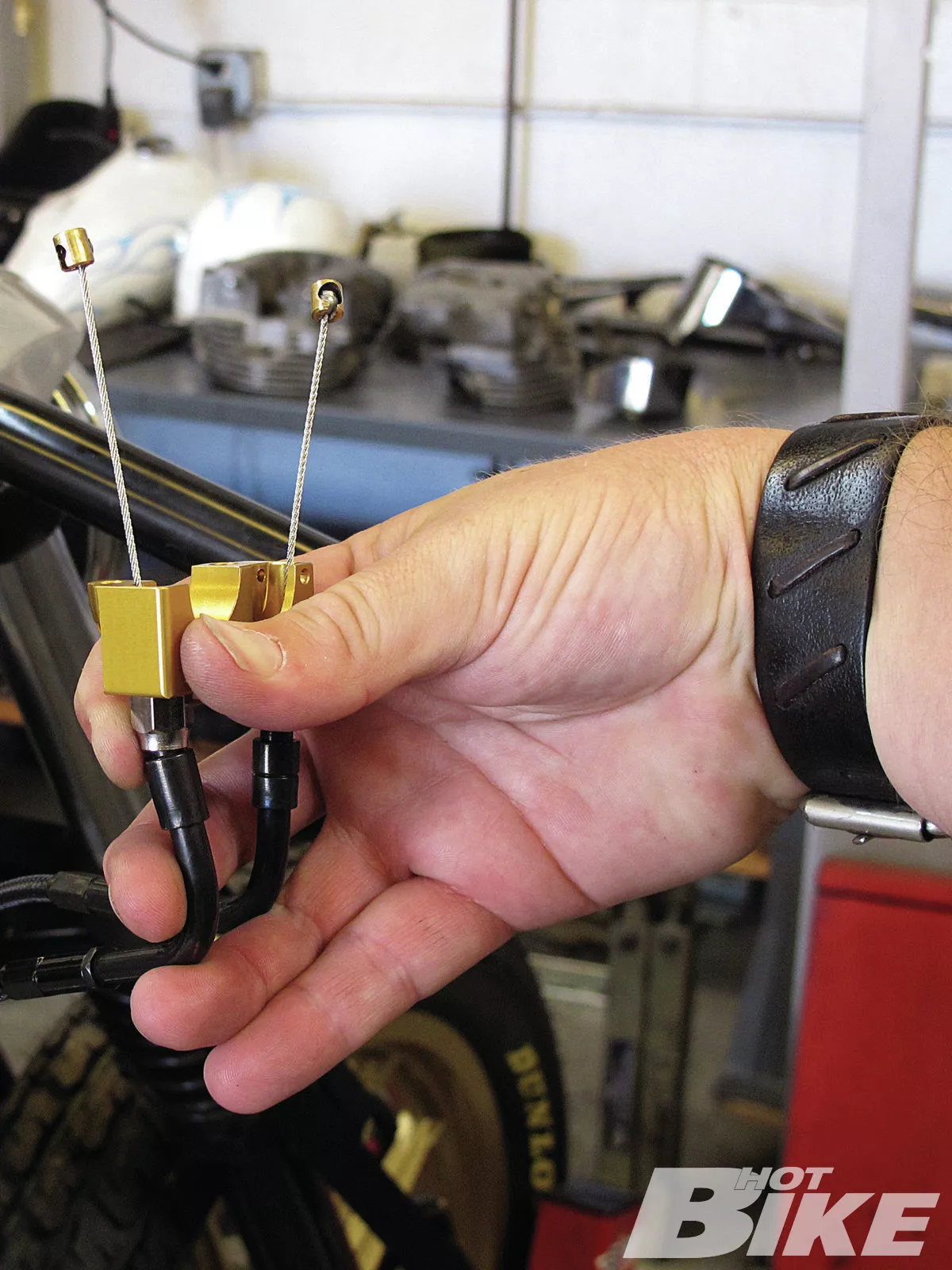
01. I had the Biltwell Whiskey Throttle housing anodized gold to match the ISR controls. To get started, I installed Barnett’s throttle/idle cables. The Whiskey Throttle comes with multiple sized ferrule inlet nuts for the varying widths of throttle cable fittings. After test-fitting the cables, I installed them and attached the supplied ferrules along with cable assembly lube.
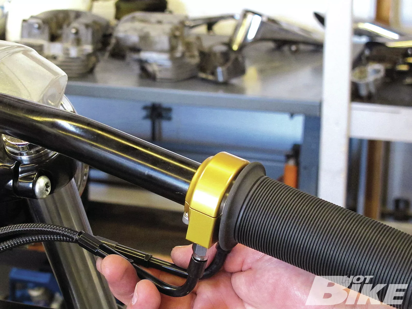
02. Once I had the cables installed, I tightened up the Whiskey Throttle assembly and fished the cables to where the carburetor will be located.
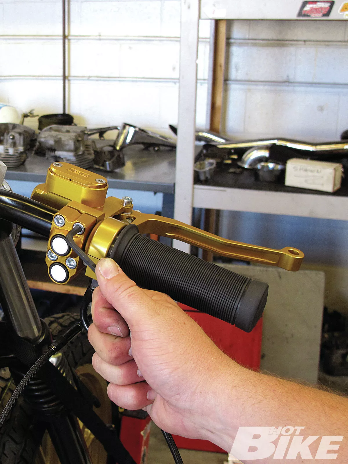
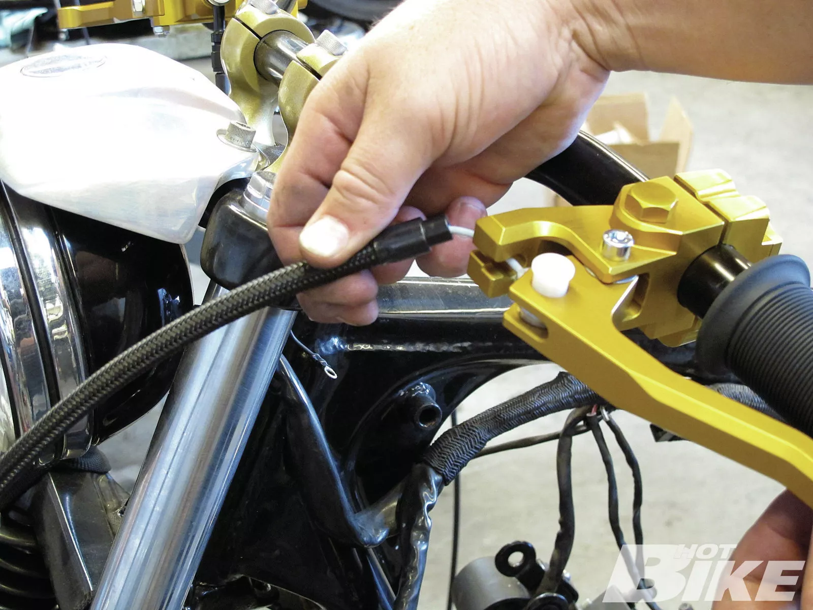
03. Moving on to the ISR controls, I wanted to mock up their positioning before wiring the switches since I needed to drill the Tracker Bar to run the wiring internally. Once I had a desired location, I moved on to installing the brake line.
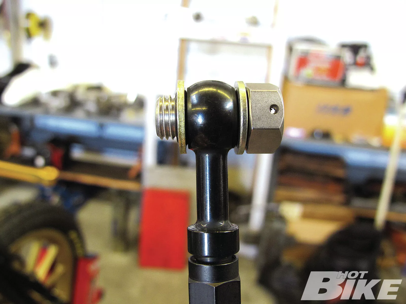
04. Here is how the ISR banjo bolt with the provided sealed washers installed through the new brake line elbow.
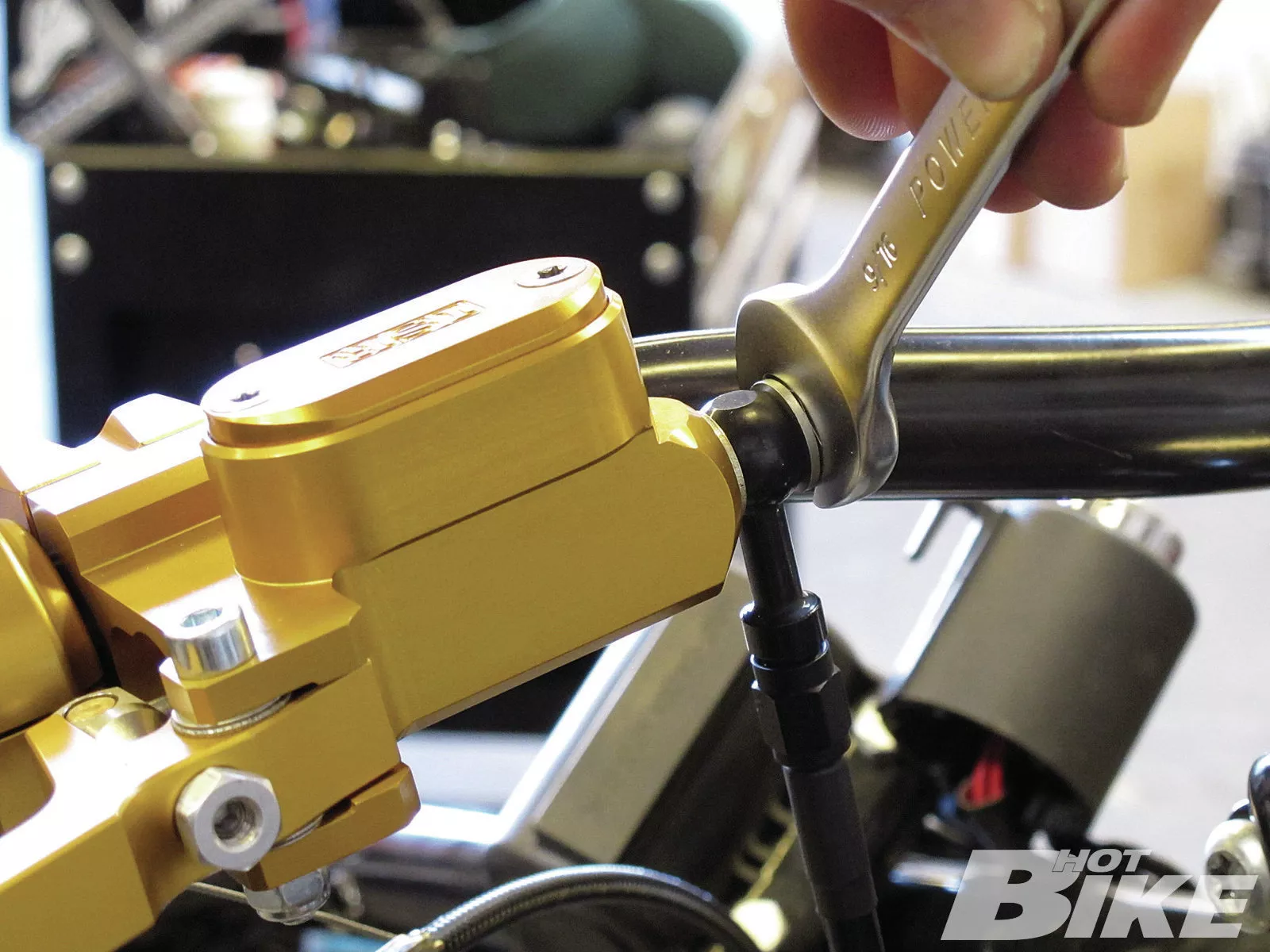
05. I tightened down the brake line to the master cylinder…
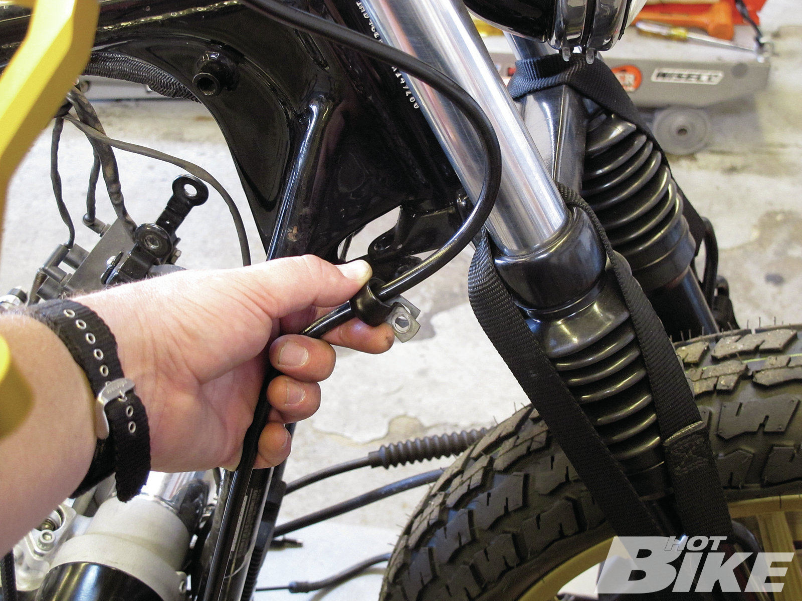
06. …and fished the line through the stock clamp under the triple tree (arrow), and to the front brake caliper.
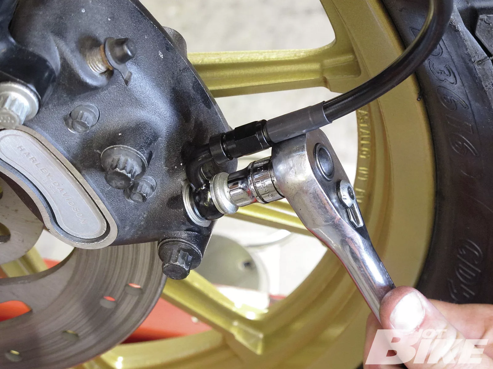
07. Next, I snugged up the 90-degree brake line elbow to the caliper and the brake line installation was complete. All I need to do when I’m ready to ride is fill the master cylinder with DOT 4 brake fluid and bleed the brakes, and I’ll be good to go.
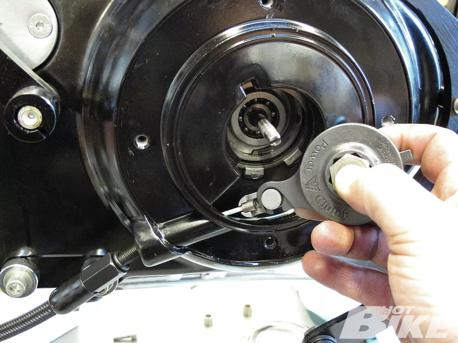
08. I moved on to installing the new clutch cable to the ball and ramp assembly. Once I re-installed the ball and ramp inside the clutch housing, I fished the cable up through its housing (located on the left side downtube) to the ISR control. After mocking up the exact location of the ISR clutch lever, I was ready to install the cable to the lever.
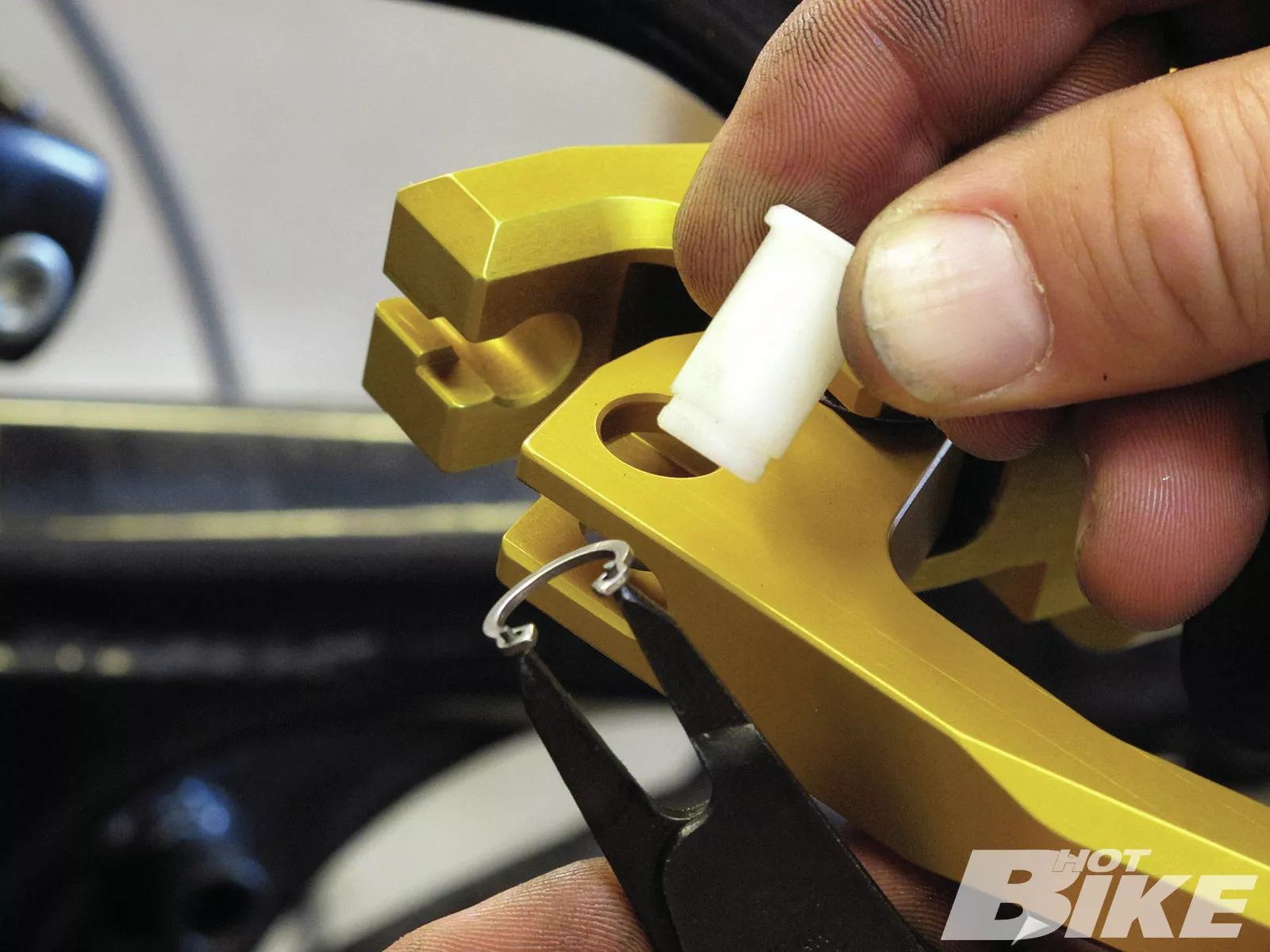
09. The clutch cable eyelet simply installs to the ISR pivot pin and is held in place with this snap ring.
10. After I installed the clutch cable eyelet to the pivot pin and I installed the snap ring, then I adjusted the clutch and installation was complete.
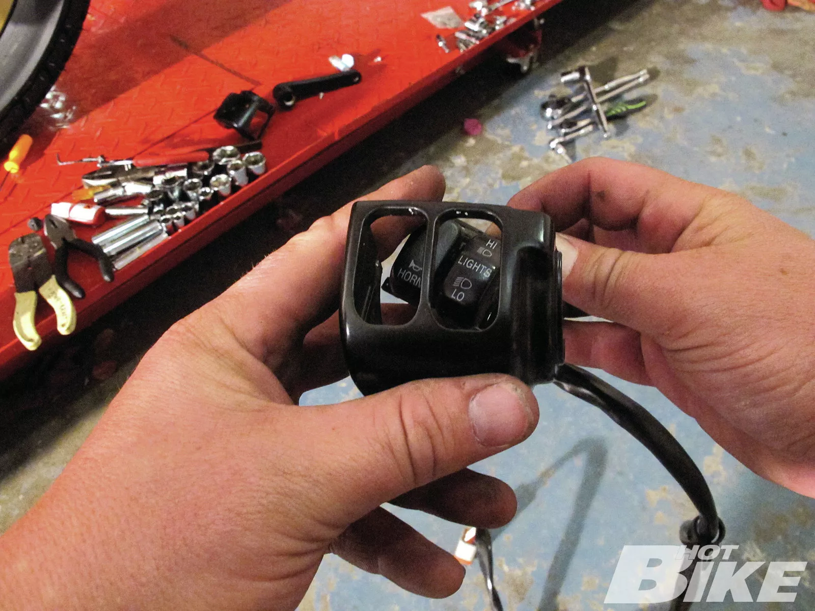
11.** Now that the controls/switches were mocked up, I was ready to wire the switches. I started by removing the wiring from the stock switch housings. My goal was to retain the factory Deutsch connectors that relay power from the switches to the ECM. Since I’m somewhat of an imbecile when it comes to electrical work, I asked Gard Hollinger from LA Choprods to help me wire the leads from the ISR switches. Why not go straight to the source, right?
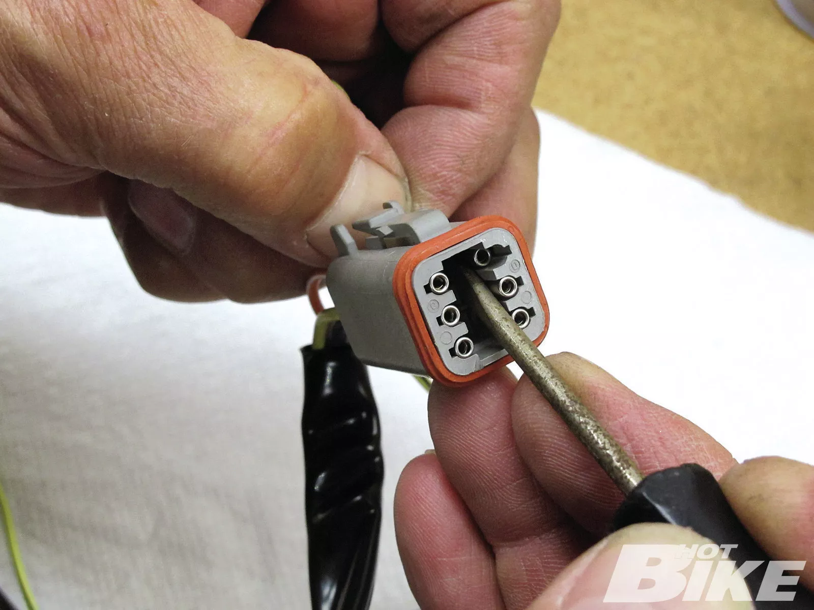
12. We had to remove the pins from the Deutsch connectors since we weren’t going to utilize the HORN and RUN functions on the Sweet Tracker. We needed to solder lead wires to the push buttons and the slide switch on the ISR switches, and then eventually solder the leads to the factor wiring, ultimately re-using the Deutsch connectors.
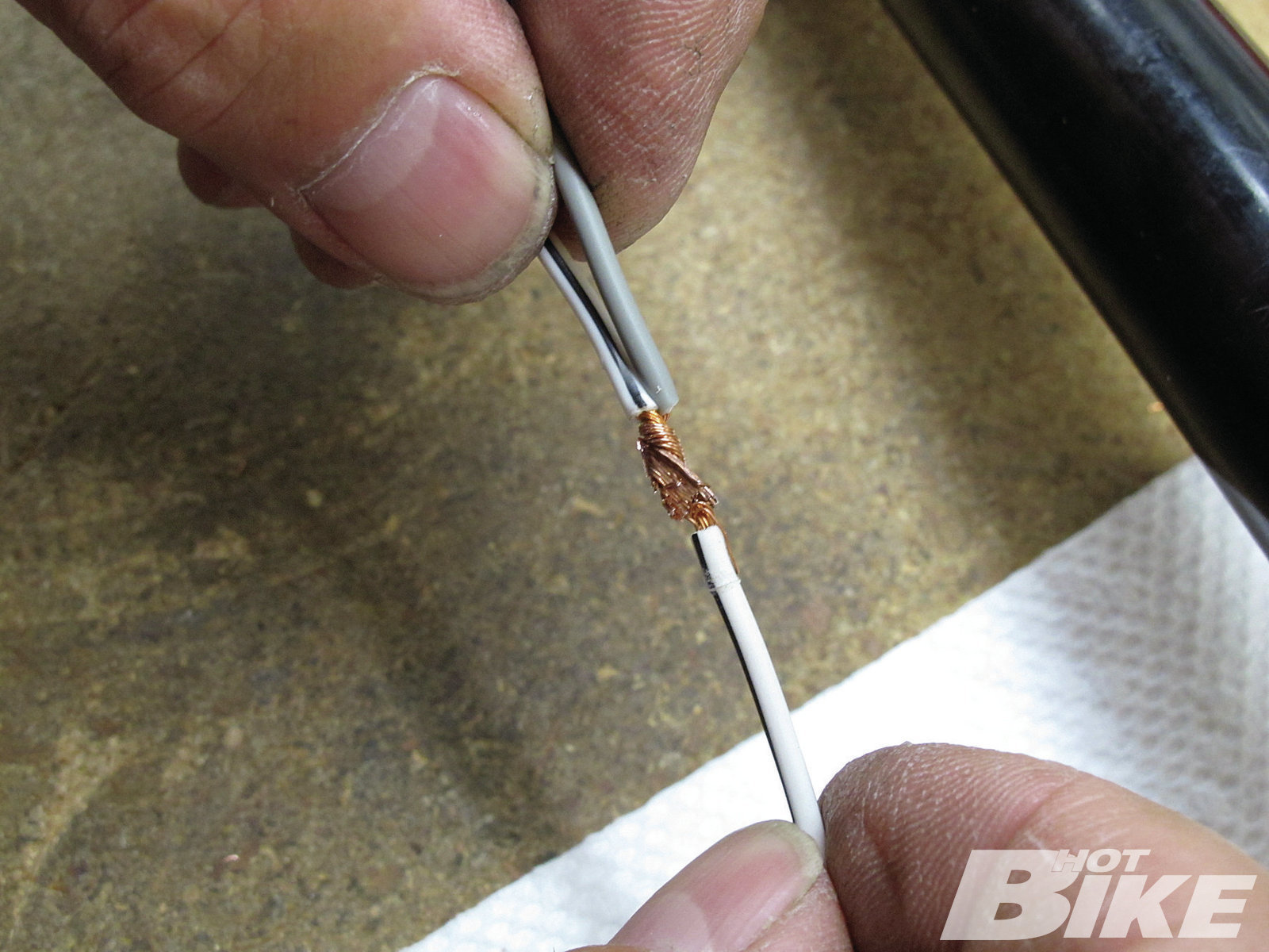
13. Because I wanted to ditch the RUN button, we had to tap its wire into the START wire. After this was done, a nice dab of solder was applied and heat shrink sealed the new connection up nice and tight.
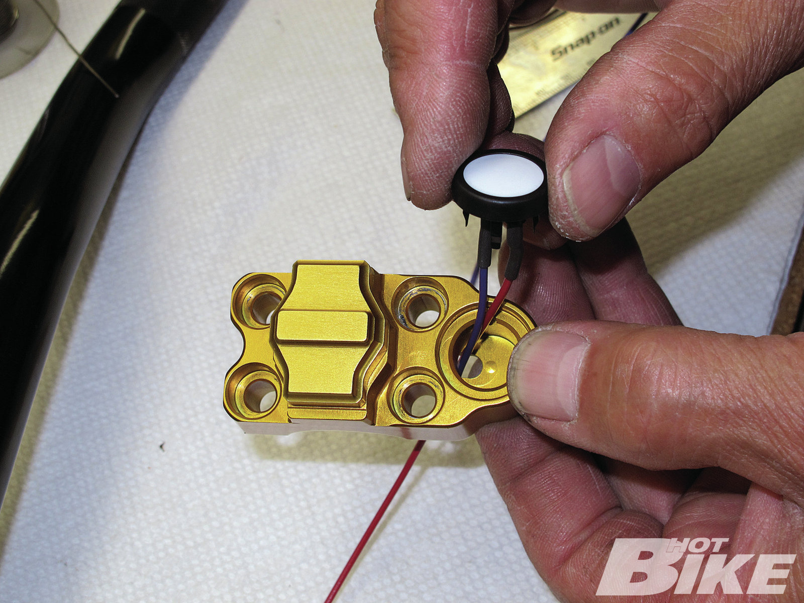
14. Starting with the right side ISR switch housing, the two push buttons were removed with a tiny flathead screwdriver. The top button: START; the bottom: TURN. Gard had plenty of wire lying around the shop so we tried to match the factory colors as close as possible. Note: You may want to color code your lead wires to the factory wire colors. Gard soldered up the leads to each push-button terminal (two per button) and coated them with heat shrink and then re-installed the buttons to the switch.
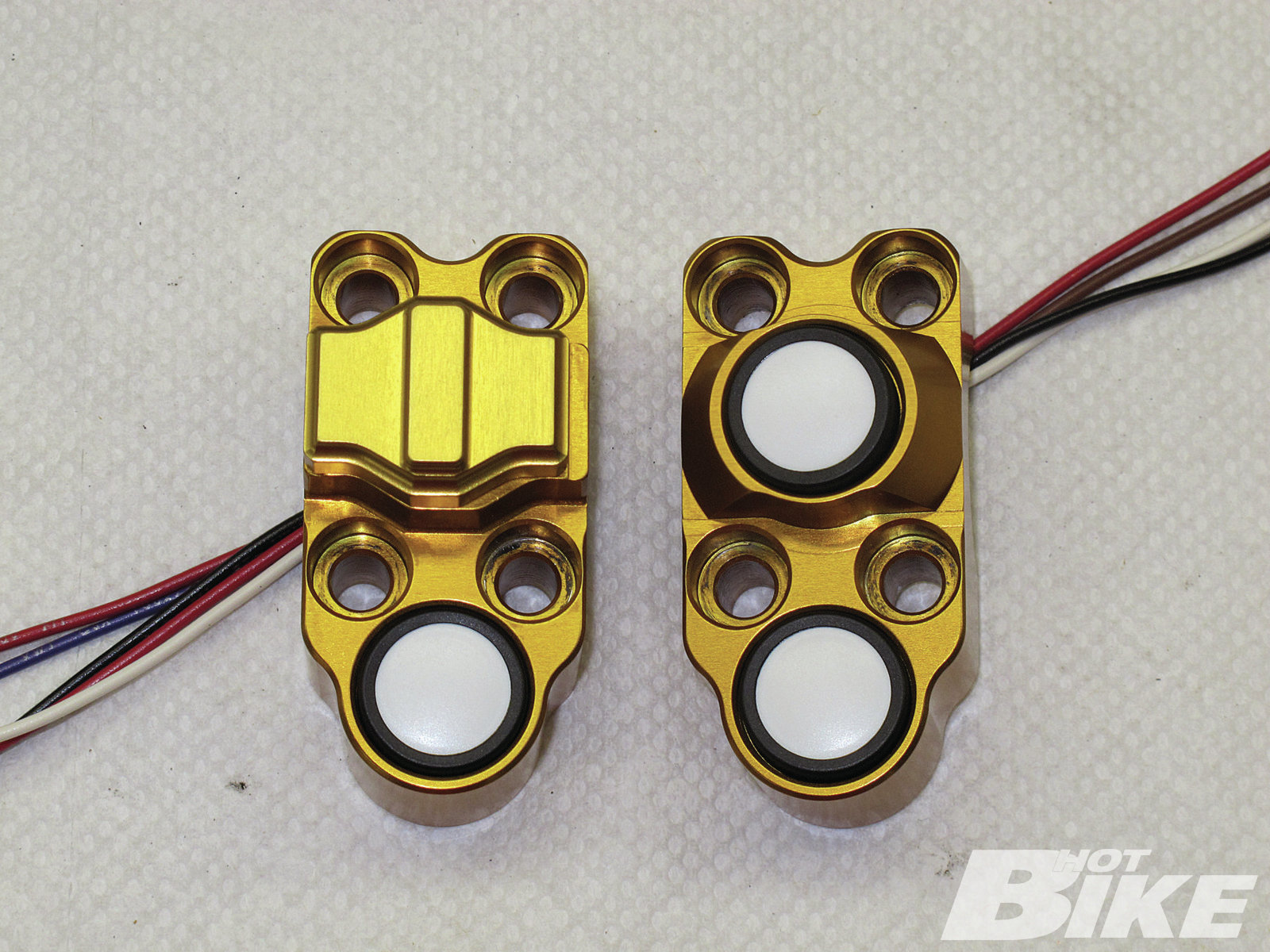
15. After repeating the same process to the push button on the left side ISR switch, Gard moved on to wiring the slide switch, which will act as the high/low beam.
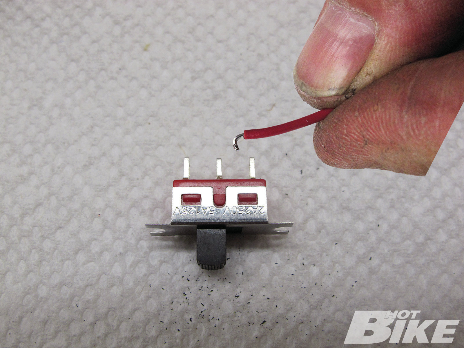
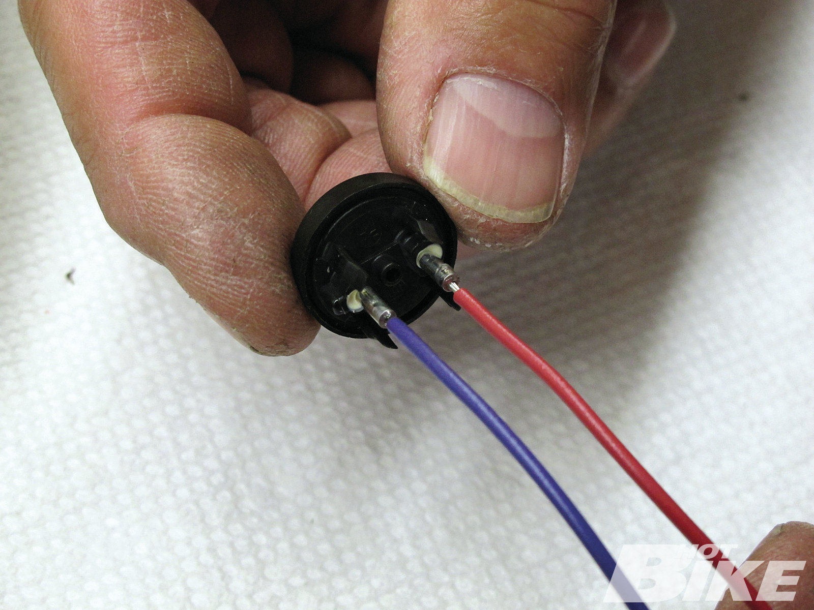
16. Gard emphasized the importance of a very hot soldering iron and that a little bit of solder goes a long way. He used a 1.5mm Allen wrench to loosen and remove the two Allen bolts holding this three-pronged terminal in place. He then tinged the end of the red lead wire with solder and bent it to hook around the switch terminal.
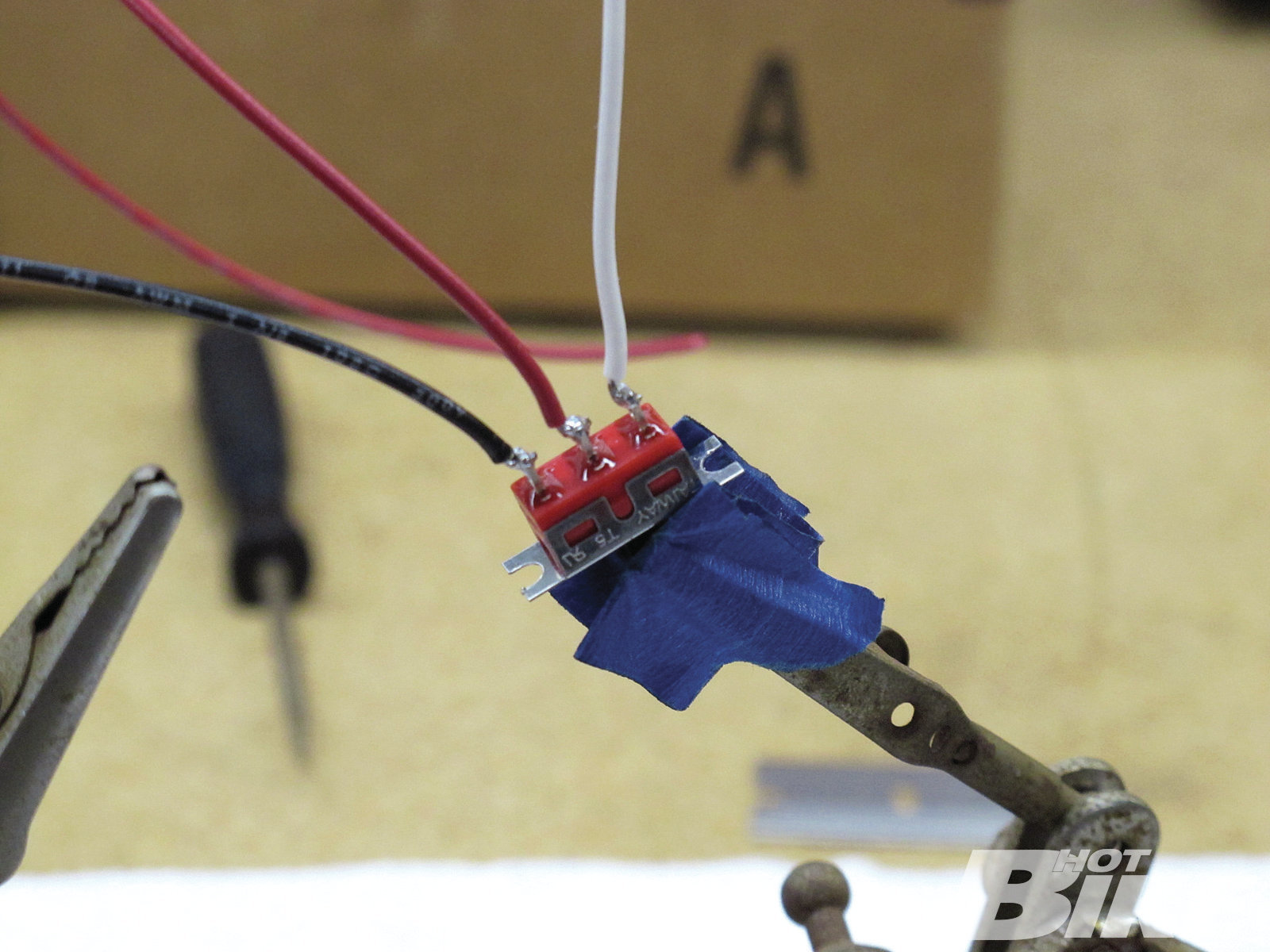
17. The red lead indicates power going into the switch (middle terminal). The black wire on the left is the high-beam wire, and the white wire on the right is the low beam wire. Once soldering was complete, heat shrink was used over the terminals to seal the new connections in place.
18. The ISR switch leads were ready to be soldered to the factory wiring. For the left switch, I’m running the left turn signal, and high/low beam functions. For the right, I’m keeping the right turn, and ditching the run wire but linking it to the start wire, so I’ll only need two push buttons. The last wiring step was to solder the leads to the factory wiring, heat shrink the connections, and then route the wiring through the bars.
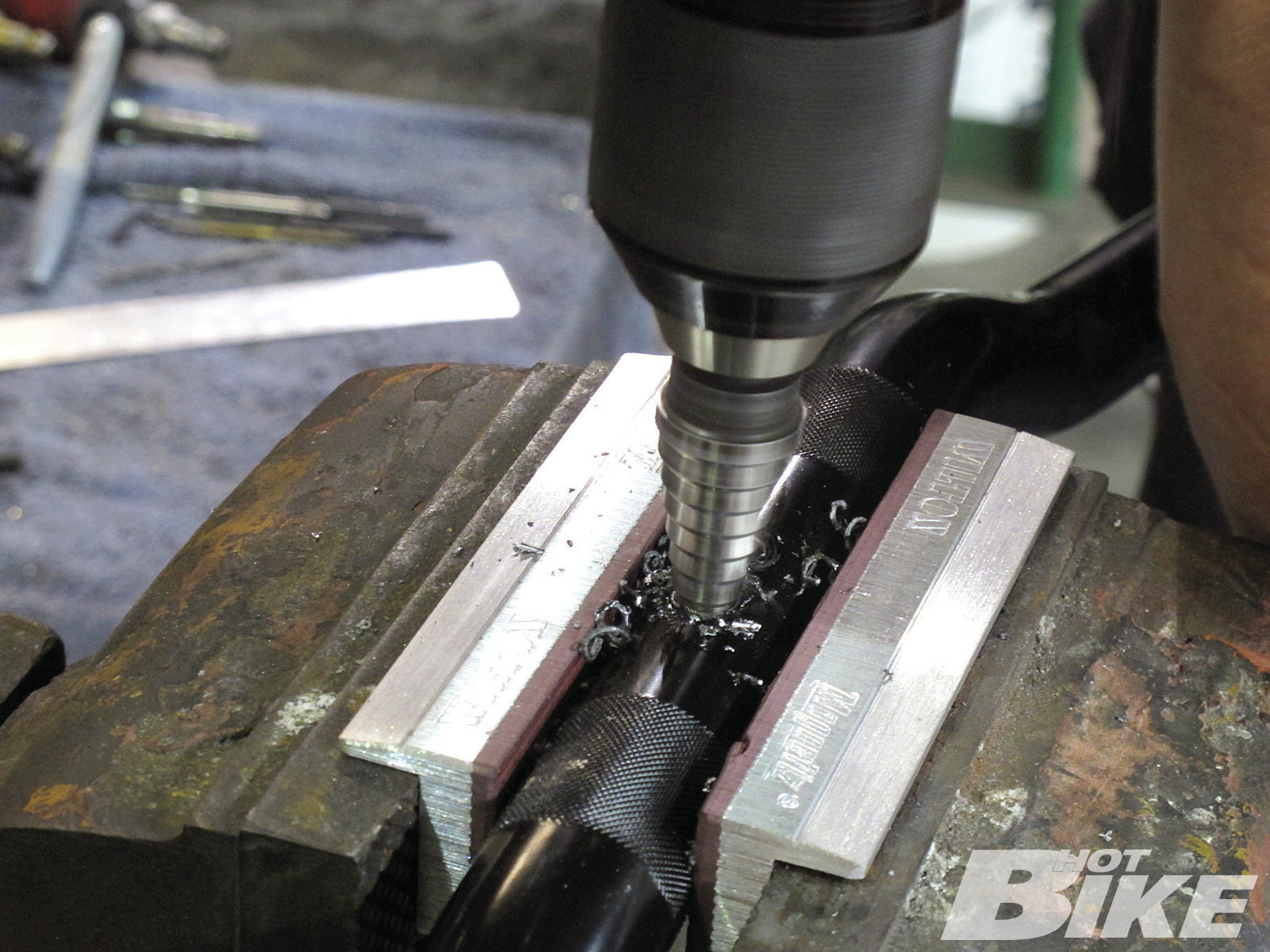
19. In order to do that, we needed to drill the bars to run the wires internally. Gard drilled a main slot in the bottom-center of the Tracker bar and two generous-sized holes in the left and right sides of the bar where the switches will mount. The center slot needs to be large enough to accept both the right and left side switch wiring. After drilling the holes, he die-grinded the holes smooth, and finished them up with the de-burring tool. Bar complete, ready for wiring.
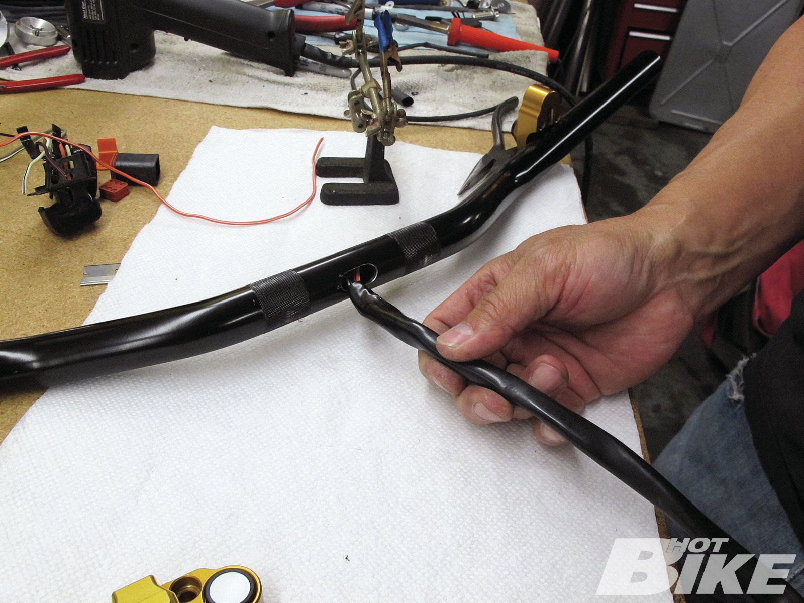
20. After fishing the left and right side switch wiring through the bar and out the center slot, the factory heat shrink was reused to cover the exposed wiring. The bar was then re-installed and ready for final assembly.
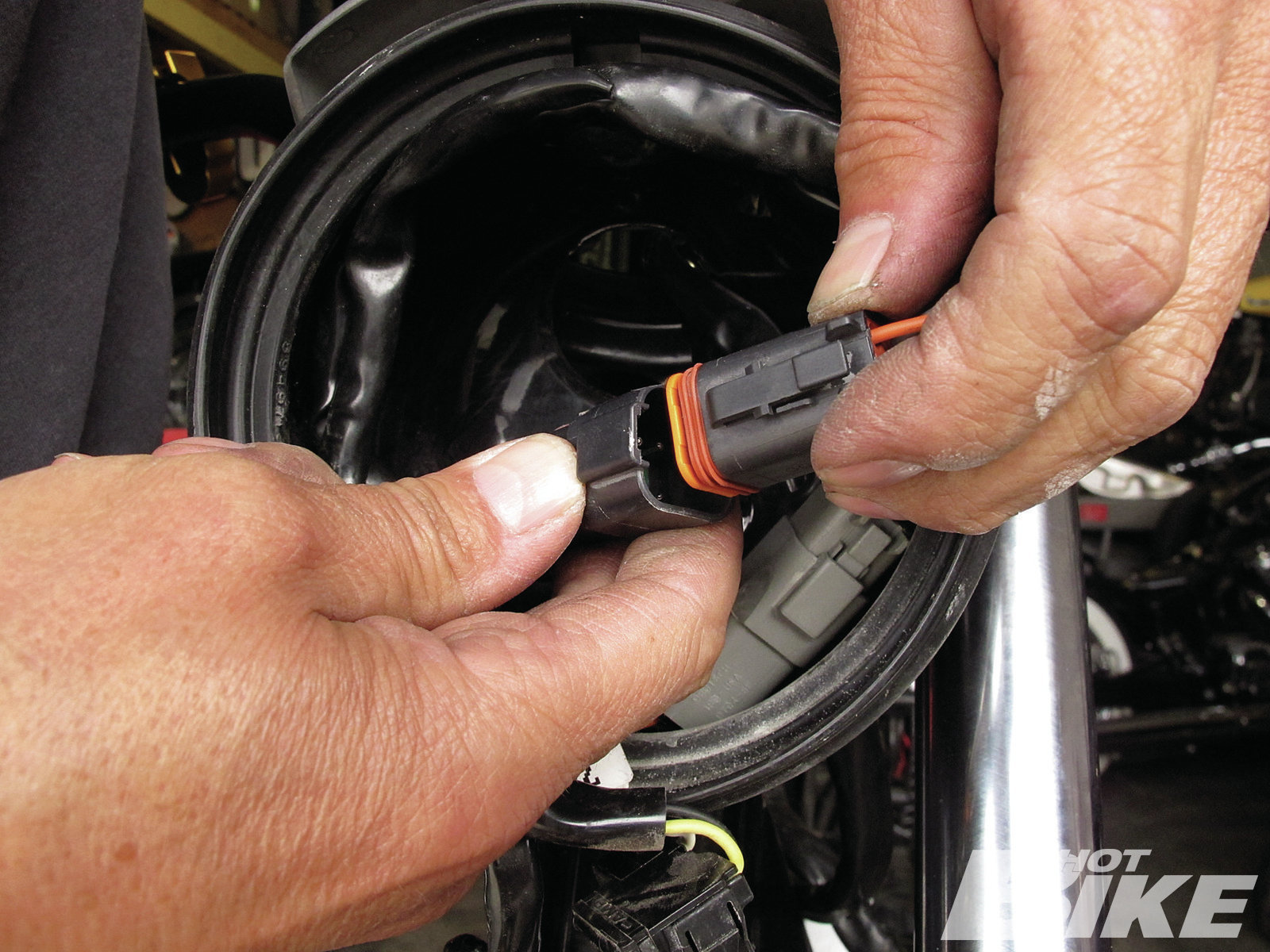
21. The factory pins were plugged back into their Deutsch connectors (one grey, one black) and routed back to the inside of the headlamp assembly.
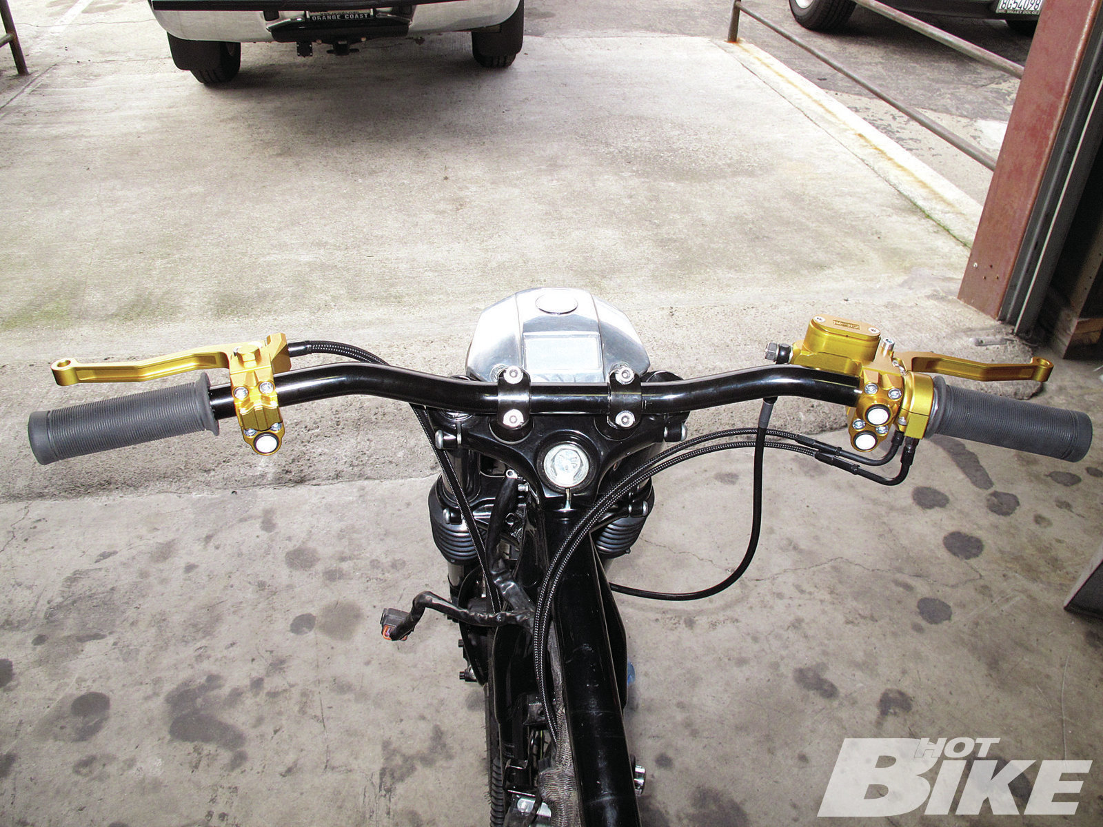
22. The switches and controls were then tightened down on both sides of the Tracker Bar and installation was complete. Overall, the wiring section wasn’t as tough as I thought, but then again I was on the outside looking in. Thanks for the lesson, Gard!
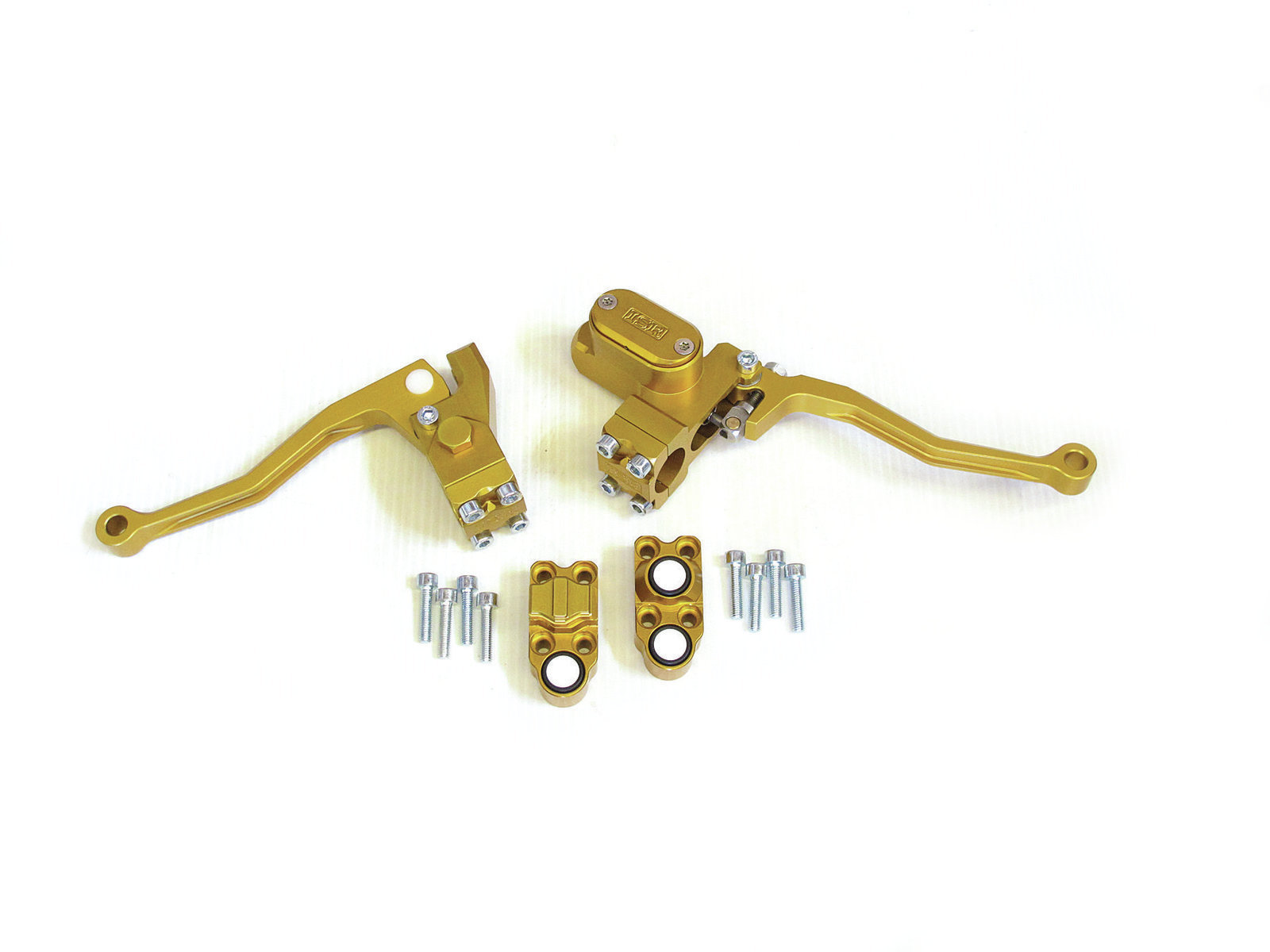
The Sweet Tracker is getting closer and closer to the finished product. I started this project with a bone-stock 2000 XL883 Sportster Hugger in hopes of transforming it into a dirt track racing replica. So far, it’s coming along as I anticipated. In the last issue of HOT BIKE, I installed the Biltwell Tracker handlebar, Whiskey Throttle Assembly, Slimline Risers, and Kung Fu Grips; however, I wasn’t sure what kind of hand controls I wanted to use. I wanted something unique that encompassed a racey aesthetic. After scouring the internet, I found the yin to the bar’s yang in the ISR Hand Controls from LA County Choprods.
The ISRs are made from high-grade billet aluminum with a certain craftsmanship that looks like months of machining went into them. They are available in clear anodize or black anodize ($25 extra), but I had them anodized gold to keep with the Sweet Tracker’s black/gold theme. Manufactured in Tumba, Sweden, by ISR Brakes and exclusively distributed in North America by LA County Choprods for the past seven years, ISR components are top-notch quality that Choprods’ sole proprietor, Gard Hollinger, utilizes for many of his own bike builds.
For the brake side, I decided on the Chopper Style Front Brake Master Cylinder ($345), which includes the lever. Adjustable levers are also available for $55 and allow palm-to-finger reach distance to be fine-tuned based on rider preference. This setup is available for right side or left side (hydraulic clutch) applications. Based on your front brake setup, master cylinders are available with 14mm bore (single two-piston caliper, or dual two-piston caliper), or the 17.5mm bore (for units requiring more volume such as four- and six-piston calipers). Both the 14mm and 17.5mm master cylinders accept a 10×1.25mm banjo bolt (ISR manufactures really trick bolts for this application for a small fee when purchasing master cylinder setup). And if you’re looking for a custom color like mine, you can chase the rainbow for $100 extra.
For the clutch side, the H-D cable-operated clutch lever assembly (starting at $165 in clear anodize) was a perfect fit. It’s designed for the standard five-speed H-D clutch assemblies and made to fit 1-inch » or 7/8-inch bars (7/8 adapters available for $14.25 each). The ISR cable clutch assembly provides smooth lever actuation and weighs almost nothing.
For controlling the electronic functions in the cockpit, I used a set of ISR switch housings: on the right, a two-push-button switch (starting at $112) will operate the right turn signal and start function. For the left, a one-push button will control the left turn signal, and a built-in slide switch will operate the high/low beam (starting at $125). LA Choprods offers multiple variations (two push/two slide; one push; one slide; etc.) and black switch housings are an extra $15. The switch housings are also made of billet aluminum and are available in clear anodize or black anodize finishes. Again, custom colors are also offered for an additional price.
To tie the new ISR controls to their corresponding components, I saw a set of matte black braided cables at the Barnett’s booth in Sturgis and knew they would be a perfect fit, so I ordered a set of throttle/idle cables ($55 each), and a clutch cable ($75). The matte-braided finish is non-abrasive so it won’t scratch and the elbows are black-chrome plated. The inner wires are made of stainless steel wire rope for durability, and the » clutch cable comes with Barnett’s high-efficiency nylon-coated inner wire for a smooth clutch operation and reduced clutch lever effort. All cables are available in stock lengths for ’87-later big twins, Sportsters, and V-Rods, and custom lengths are also available. Because I needed a custom set of cables, for the throttle/idle cables I ended up with a 28-inch outer casing and a 32-inch inner cable with 90-degree bends at the elbows. For the clutch cable, I needed a 49-inch outer casing and a 53-inch inner cable (4 inches of travel in the clutch housing).
After the installation of the ISR controls and switches, along with the Barnett control cables, I’ll be one step closer to finishing the project. Follow along as I show you how the components look on the Sweet Tracker and how they were installed. Stay up to date with the build process on the HOT BIKE Facebook page (facebook.com/hotbike). HB
Source:
Barnett Tool & Engineering (805) 642-9435 | barnettclutches.com
LA County Choprods
(310) 353-2467 | lachoprods.com


