
Cylinder-Head Science
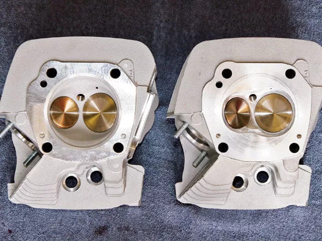
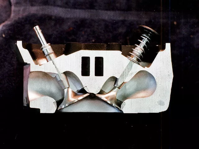
1. A high-flowing cylinder head is crucial if an engine is to reach its maximum potential and make big power numbers. Port and valve sizes should be matched to the engine displacement and rpm band. A small, compact combustion chamber; centrally located spark plug; and generous amount of dual-squish areas is highly desirable. Shown is a shallow hemi-style chamber on the left and a kidney-shaped chamber on the right.
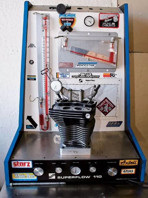
2. A flowbench is an invaluable tool commonly used by head porters for measuring port flow and characteristics. Although a flowbench can be a good indicator of port performance, it measures a steady flow, yet the engine never exerts a steady draw on the port. This is one reason why high flowbench numbers are not a guarantee that an engine will make big power. The only way to know for sure is to dyno or race-test an engine.
3. The combustion chamber is a crucial component to high flow and optimized combustion. The chamber is defined on the top by the cut-out area in the cylinder head and on the bottom by the piston dome. A small, compact chamber that does not shroud the valves, centralized spark plug, and generous squish area are highly desirable.
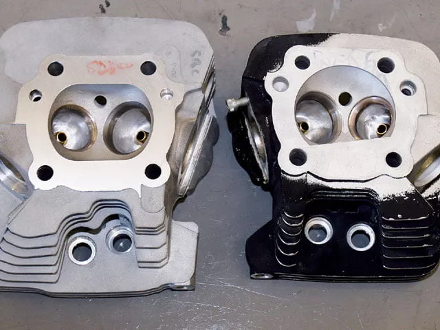
4. Combustion chambers are available in various designs. Short Block Charlie (Tempe, AZ) TIG-welded this stock Twin Cam head casting to form a compact bathtub-style chamber and 20-degree squish band that will be mated with a matching angle-top piston.
5. Short Block Charlie sectioned this Twin Cam head casting to show a cross-section of the port design. Twin Cam ports are relatively short in length compared to a shovelhead port. Consequently, measuring the port volume of two different head designs will not yield a valid comparison. Comparing port volumes only works with heads of the same design. Instead of comparing port volume values, measure port cross-sectional dimensions.
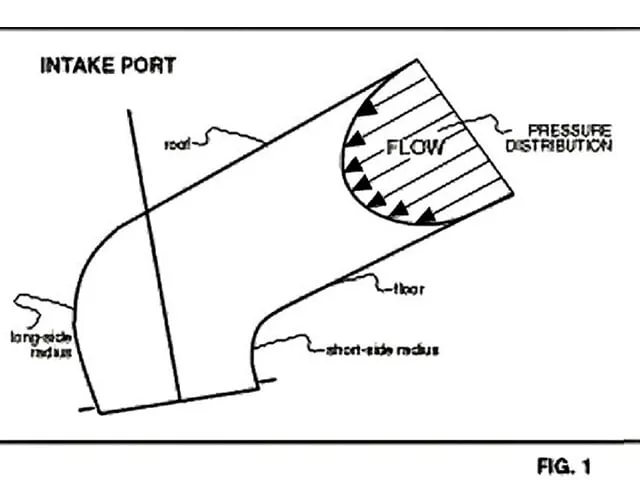
6. Pressure and velocity distribution are near symmetrical at the port’s mouth. However, as flow changes direction at the radius, velocity and pressure become less uniform. Velocity becomes higher and pressure lower on the long-side radius. Increasing the size of the port equally around its circumference will reduce velocity. In contrast, removing material only in selected areas can increase velocity in high-pressure areas, leading to increased flow.
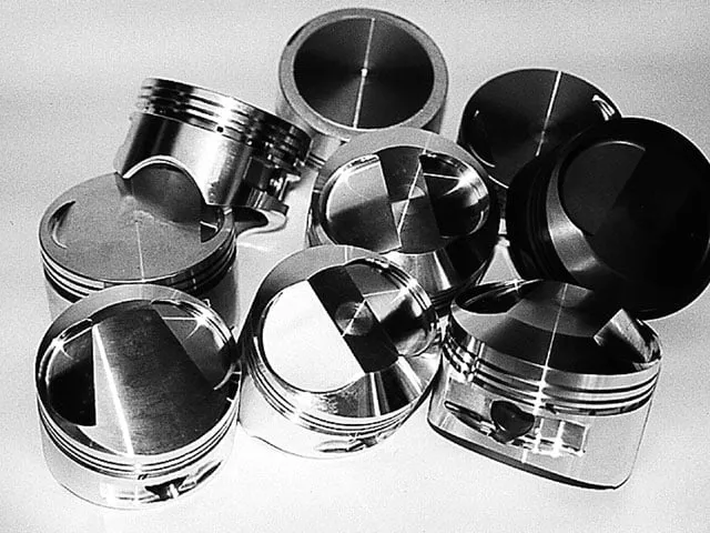
7. Piston dome shape must be matched to the combustion-chamber design and desired compression ratio. Common dome designs include flat-top, domed, and dished. Keep squish clearance tight, usually .030″ to .040″, for a street engine with steel rods and aluminum cylinders. Also, eliminate any nooks and crannies creating dead spots for the air/fuel mixture.
8. Match the camshaft to not only the engine displacement and rpm band, but also the cylinder head’s airflow characteristics and exhaust system. A weak exhaust port or restrictive exhaust system can often be improved by using slightly longer exhaust duration than intake duration.
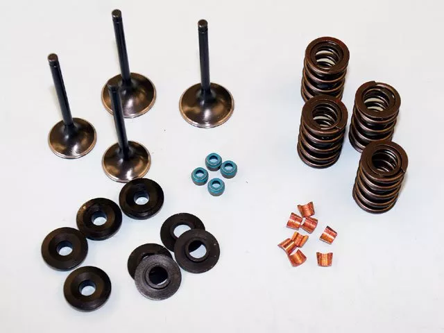
9. The valvetrain is often neglected when selecting a cylinder head. Make sure the valvesprings are compatible with the cam lobe and installed at the correct height to satisfy the cam lift and required seat and over-the-nose pressures. Sufficient spring pressure will produce optimized power through proper valve control.
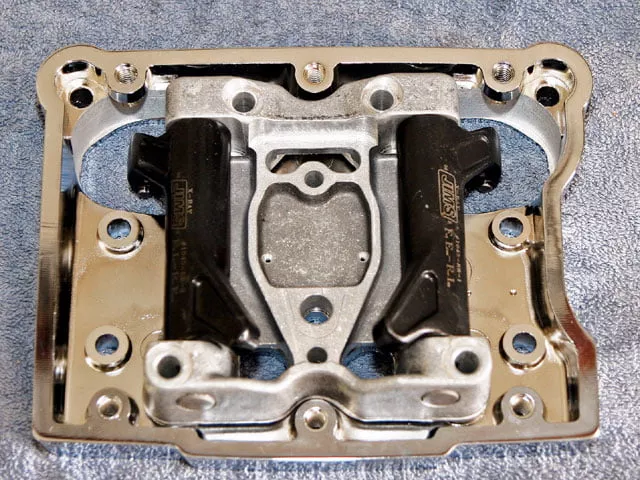
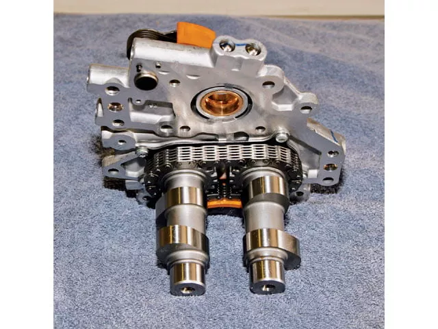
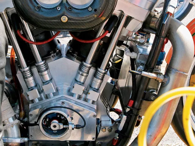
10. Rocker-arm position on the Harley 45-degree V-Twin is parallel to the axis of the crankshaft. Note that these rocker arms for a JIMS 120ci Twin Cam engine are also parallel to one another. Compare the angle of this Twin Cam rocker layout to the angle of the rockers on the Jesel Pro Stock V-Twin racing heads (photo No. 11).
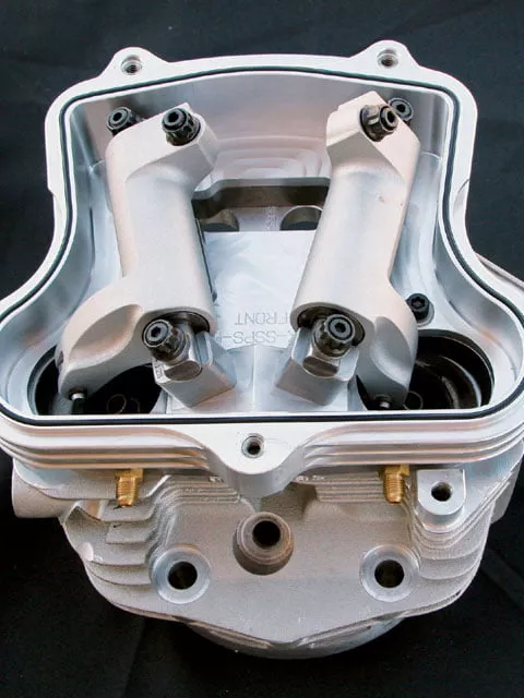
11. Head designers sometimes offset valve location and change valve angles to accommodate larger, shorter, and straighter ports, along with less shrouding by the combustion chamber. Note that this Jesel head has aluminum rocker arms, which are not parallel to one another as on conventional V-Twin cylinder heads. The head is fitted with 2.7-inch intake and 2.0-inch exhaust valves designed for high-rpm 160ci-and-larger V-Twin engines.
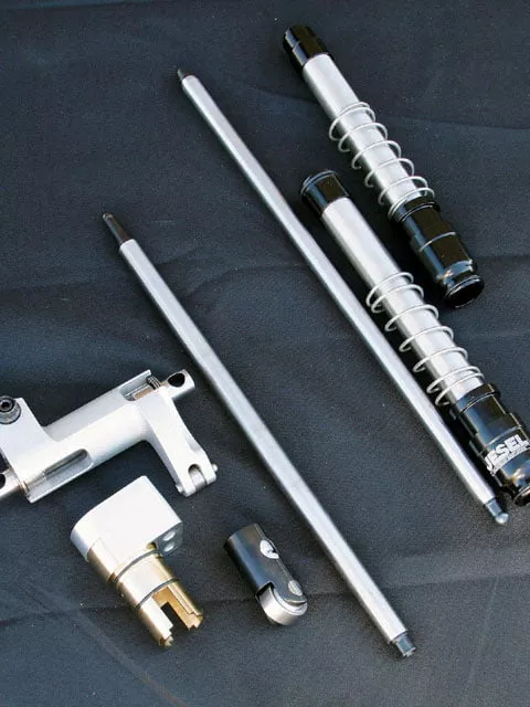
12. Shown are some of the valvetrain components for the Jesel V-Twin cylinder head. The rocker arms are made from shotpeened 70-Series aluminum, while the pushrods are either 9/16-inch or 1/2-inch diameter and straight-wall or dual-taper design to withstand high spring pressures and reduce harmonics transferred from the lifter to the rocker arm.
13. Ideally, V-Twin pushrod angles should be kept as straight as possible for accurate geometry. Moreover, the valvetrain should be made ridid and stiff to reduce pushrod deflection and stabilize the valvetrain at high rpm.
Open almost any performance catalog, and a plethora of high-flow cylinder heads pops up. Performance enthusiasts welcome the huge head selection with open arms because it offers a wealth of performance options. The downside is that there is a confusing array of options to choose from. The easy way out is to buy a “crate” engine or performance upgrade kit. However, that doesn’t separate you from the pack. Instead, it makes you part of the pack. We all know that more airflow makes more power, and bigger ports and valves flow more air. Well, that clich is only true up to a point, because other critical factors come into play. The quality of the airflow, the direction and velocity of the airflow, and the quality of combustion also play major roles in the production of power. This article will take a quick look at some of the important factors that should be considered in cylinder-head selection.
A flowbench is a tool typically used to evaluate induction and exhaust systems by providing an airflow reading in cubic feet per minute (cfm). Flowbenches are designed to measure steady-state airflow movement, but raw airflow readings have some limitations because a running engine never exerts a constant draw on either the intake or the exhaust port. What this means is that simply increasing airflow volume does not necessarily result in a power gain. Instead, it only determines the potential for a power gain. This is because increasing horsepower is dependent on not only the quantity of airflow, but also the quality of the airflow. Unless additional airflow is developed in a manner that promotes combustion, a power increase will not be realized.
Cylinder heads are a substantial investment but offer enormous potential for increased power when properly matched to engine displacement, rpm range, camshaft, induction, and exhaust system. Good cylinder heads are one key factor for good performance because they play a key role in managing airflow through the engine. Air flows through the induction system because a pressure differential exists between the cylinder and atmosphere. The differential moves the intake charge past the carburetor or fuel-injection throttle body, through the intake manifold and port, and finally into the cylinder. Valves fitted in the combustion chamber are used to control and direct the flow of the intake and exhaust mixtures into and out of the cylinder. These valves are also required to tightly seal the high combustion pressures within the cylinder during engine operation. Because the exhaust charge is at a higher temperature and pressure than the intake charge, the exhaust valve is typically only about 80 percent the size of the intake valve. Cylinder-bore diameter and valve spacing are the determining factors for maximum valve size.
Once the engine’s displacement, compression ratio, most important rpm range (low, mid, or high), and maximum rpm are determined, other parameters such as airflow requirements and camshaft specifications can be determined. Key considerations for cylinder-head selection include airflow capacity and compatibility with other engine components, although exterior aesthetics also play a part with some engine builders.
Airflow Requirements
Engine airflow requirements are primarily determined by displacement, rpm, and the desired performance level. The larger the displacement, higher the rpm, and greater the desired performance level, the greater the airflow requirement. However, keep in mind that there is a crucial relationship among port size, airflow, and horsepower.
When selecting cylinder heads, the engine’s performance level can be equated to volumetric efficiency (VE). Low- and moderate-performance engines that are naturally aspirated and run on gasoline will have a VE under 100 percent, usually in the 60-90-percent range. This means that during engine operation, the cylinder will be filled to less than its capacity, or less than 100 percent. Serious performance engines typically achieve 100- to 110-percent VE, with some in the 120-percent or higher range. But these engines need high-flowing heads (and induction systems) to achieve the high VE.
It’s important to understand that two engines with identical displacements may have different airflow requirements. For example, assume one engine is designed to achieve 1.5 horsepower per cubic inch, while the other only achieves 1.0 horsepower per cubic inch. The engine that makes 1.5 hp/ci will have a higher VE; consequently, it will require greater airflow than the less powerful engine. Another point worth noting is that greater airflow capacity will not necessarily improve an engine’s performance and may even reduce it due to lower-velocity ports, especially at low rpm. For that reason, the “bigger is better” theory does not apply to cylinder-head selection.
Insufficient airflow for the engine displacement is a common problem with many newly purchased bikes with big-bore/stroker kits installed. If we assume your engine displacement requires 170 cfm of airflow at 6,000 rpm and your cylinder heads only flow 150 cfm, you have three options: (1) modify the head’s ports and valves to flow 170 cfm, (2) select a different set of heads that flow 170 cfm, or (3) accept less than maximum performance from the 150-cfm heads.
Heads that flow less than the total required airflow will produce great low and midrange power, but power will fall off quickly at high rpm. This is what happens when engine displacement is increased through boring and/or stroking, yet the cylinder heads (and/or induction system) remain stock.
A classic example of this condition is bumping up a Twin Cam 88 engine to 95ci but retaining the stock heads and cam. The engine will have great torque down low and at midrange rpm, but horsepower takes a nose-dive around 5,000 rpm. The engine will fall flat on its face and top out at only 75 hp (0.79 hp/ci) because it runs out of air at high rpm. In this example, the parts combination is more incomplete than it is incompatible.
However, it’s important to keep in mind that peak flow numbers are only part of the airflow story. Good low- and mid-lift flow figures are also important, because a valve spends less time at peak lift than at low- and mid-lift. For example, a valve only reaches maximum lift once during opening and closing but passes lower-lift points twice: once during opening and again during closing. For these reasons, cylinder heads cannot be accurately compared solely by peak flow numbers. Although impressive peak flow numbers may sell parts, it’s flow under the entire lift curve that accelerates your bike. It is acceptable to use peak flow numbers when matching a cylinder head’s airflow potential to the required airflow for a given engine displacement and performance level, but not when comparing one head to another. The correct method for comparing airflow between various cylinder heads is to add up the flow numbers at all measurement points and use the total value for comparisons. Nevertheless, it’s critical to remember that port velocity (discussed below) is another important airflow consideration.
Ports
Port size and design can have a major influence on both the horsepower and torque curves. A critical factor for producing good power curves is a cylinder-head port that provides adequate mass flow and velocity for the engine requirements. Up to a point, the higher the airflow velocity, the more efficiently a port will fill the cylinder. A larger port or valve may flow more air at high valve lifts but can result in less flow velocity at low rpm. Such conditions will produce poor torque numbers until the velocity increases at higher engine speeds.
Ideally, you want the smallest port cross-sectional area that satisfies the engine’s airflow requirements for the most important rpm range-in other words, the smallest port with the highest flow. For a street engine, this will keep port velocity high at low rpm (below peak torque rpm), resulting in lots of torque at low and midrange speeds while accelerating the bike the fastest. High-velocity ports also improve throttle response, fuel economy, and driveability.
Determining port velocity values (usually feet/second) requires the use of a velocity probe connected to a flowbench and ideally includes a velocity map of the entire port cross-section. However, note that port velocity figures are hard to come by in the Harley performance world because many performance engine builders do not check or publicize them. Your best source is often a knowledgeable head porter specializing in serious performance work.
A port’s peak velocity number is not necessarily the entire story, similar to airflow numbers where peak flow is not the whole story. Velocity distribution within the port is also important. High-efficiency ports will often show that roughly 90 percent of the port flows at 90 percent or greater of peak velocity. This is where a velocity map of the port becomes important.
Another point to note is that velocity numbers are relative to a given flowbench; therefore, they cannot necessarily be compared accurately to values generated on a different flowbench. By now, you should know there are many subtleties beyond only peak airflow numbers that distinguish a good-performing head from an average or even a poor head.
Another important cylinder-head consideration is to have a balanced flow between the intake and exhaust ports. Hence, it is wise to evaluate a cylinder head’s overall flow and not just intake flow. Although most attention is given to intake-port flow numbers, exhaust flow numbers are also important because there is a critical relationship between intake and exhaust flow. A head with an excellent intake port can be handicapped by a weak-flowing exhaust port, and the engine will never achieve its full power potential. One method for evaluating an exhaust port is to divide the exhaust flow by the intake flow at the same valve lift (better yet, the total flow at all lift increments) to determine an exhaust-to-intake (E/I) flow ratio. In general, stock cylinder heads have between a 60- and 70-percent E/I flow ratio, moderate performance heads a 70- to 75-percent ratio, and serious performance heads a 75- to 85-percent ratio. Too much exhaust flow can over-scavenge the cylinder and waste power. Most performance engine builders prefer a 75- to 85-percent E/I ratio. As a general rule, the higher the E/I ratio, the more top-end horsepower is favored at the expense of low-end torque.
Valves and Seats
The shape of the valves, along with the angles and widths on the valves and valve seats, has a tremendous influence on airflow volume and quality and is closely related to port design and cylinder filling. A specific valve job has an important relationship to how the air flows around the seat and enters the combustion chamber, how the exhaust gasses exit the chamber, and how they interact. As a result, seat angles and back-cuts on valves can drastically alter potential flow values and power.
Port design, particularly the short-side radius area, has a significant influence on how airflow is directed at the valve head. Often you will notice a slight bump on the port floor at the short-side radius. The bump is designed to increase the speed of the air/fuel mixture as it is making the turn, which helps keep the fuel suspended in the airflow so it doesn’t puddle on the port walls. A bump is also used to help direct the air/fuel mixture toward the valve head instead of the wall of the port bowl. Due to inertia, air does not easily make sudden changes in direction, so changing angles and widths of the valve and valve seat or changing port design can improve or degrade performance. For these reasons, it is crucial that the valve shape, seats, port bowl, short-side radius, and walls of the ports are matched to one another.
Combustion-Chamber Design
The size and shape of the combustion chamber is determined by the cylinder head and piston design. Combustion-chamber design has a significant effect on flame travel, combustion efficiency, compression ratio, detonation limitations, exhaust emissions, and ultimately power production.
Some heads are designed with compact, swirl-inducing kidney-, heart-, or asymmetrical-shaped chambers that increase air/fuel mixture activity, thus promoting a more homogeneous mixture distribution and more complete burn of the intake charge. Locating the spark plug as close as possible to the center of the bore will shorten flame travel and speed up combustion. These design features result in faster combustion and improved efficiency. High-efficiency chambers often require less ignition timing to make power, do it with less fuel, and produce less exhaust emissions.
Fitment of Components
In addition to airflow requirements and chamber design, cylinder-head selection must also consider fitment to other components. For example, if you are installing large-bore cylinders, such as 3-13/16 inches, 4.0 inches, or larger, make sure the head bolt pattern will support your bore size and crankcase stud pattern. Some aftermarket heads include raised ports for improved airflow and cylinder filling, but they may require special induction and exhaust systems for proper fitment and clearances around the chassis and fuel tank. In addition, cylinder-head oil returns and breather vents must be compatible with the oil and venting conventions of the cylinders and crankcase. Be sure to coordinate these specifications when selecting heads, cylinders, and crankcases.
Valvetrain
Another important cylinder-head consideration is the valvesprings. The objective for valvesprings is to delay valve float beyond the engine’s normal operating range. Valvesprings must be matched to the valve lift, aggressiveness of the cam lobe design, weight of the valvetrain, and maximum engine rpm. Additionally, every cam lobe profile generates certain harmonics that requires a compatible spring. Although a generic spring in an aftermarket head may satisfy pressure and installed height requirements, it may not be compatible with a given cam lobe due to harmonics.
Since the valvespring and camshaft must work together, make sure springs compatible with the cam lobe are used and installed at the correct height to satisfy the cam lift and required seat and over-the-nose pressures. Sufficient spring pressure will produce optimized power through proper valve control. Conversely, too much spring pressure unnecessarily increases friction and valvetrain wear while reducing power. Excessive spring pressure can also cause a hydraulic lifter to collapse, reducing lift, duration, and power.
Signs of incompatible valvesprings include excessively worn or broken parts and mysterious dips in the power curve at some point in the rpm range that do not respond to induction or exhaust-system tuning changes. Some professional engine builders have found that cryogenically freezing valvesprings before installation can roughly double their life in a serious competition engine.
Certain cylinder-head and cam combinations may require long-stem valves to achieve the proper spring spacing. Since higher-ratio rocker arms will increase valve lift and open the valves faster, stiffer springs may be required, and valve-to-valve and valve-to-piston clearances must be checked. Regardless of whether you’re buying pre-assembled heads or assembling them yourself, make sure the valvesprings satisfy the necessary requirements.
Years ago, racers typically made valvetrain parts as lightweight as possible. Frequently, the result was broken rocker arms, bent pushrods, inaccurate valve timing, and an overall reduction in power. Today, knowledgeable engine builders strive for stiffness and rigidity in the valvetrain over reduced weight. Heavier, large-diameter, thick-walled, dual-taper pushrods have proven to provide more accurate valve timing and durability than flimsier counterparts.
Final Thoughts
When hopping up an engine, remember that there is a key relationship among engine displacement, rpm, airflow, and horsepower. Always think in terms of building an engine from the bottom up but designing it from the top down. Once engine displacement, bore/stroke geometry, rpm, and application are known, the appropriate cylinder head can be selected.


