
Easy Riding | LegUp Landingear Install
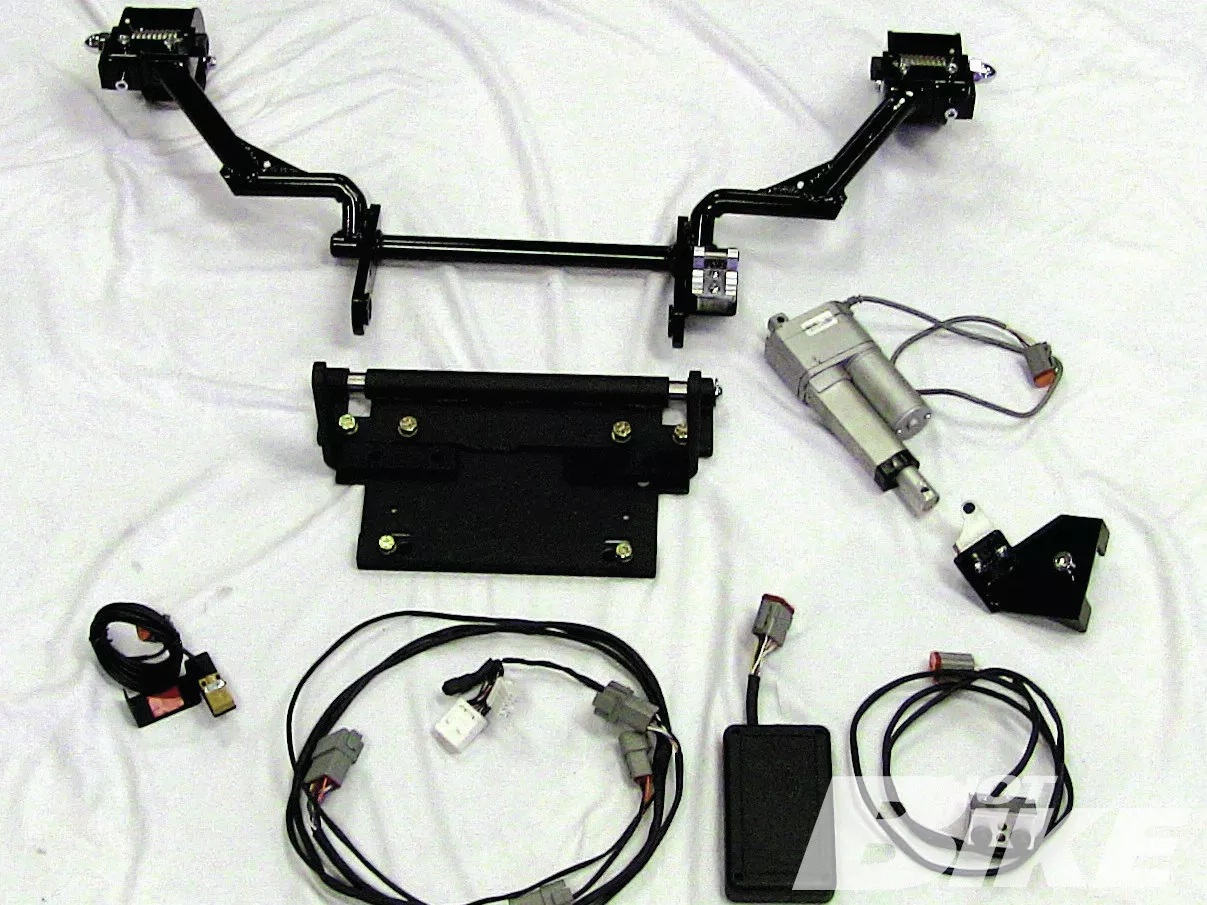
These are the components that make up the LegUp system that fits H-D Touring models ($2,995). Also included in the box are a 25-page installation manual that is full of pictures and a user’s manual. Installation is a complete bolt-on affair.
These are the components that make up the LegUp system that fits H-D Touring models ($2,995). Also included in the box are a 25-page installation manual that is full of pictures and a user’s manual. Installation is a complete bolt-on affair.
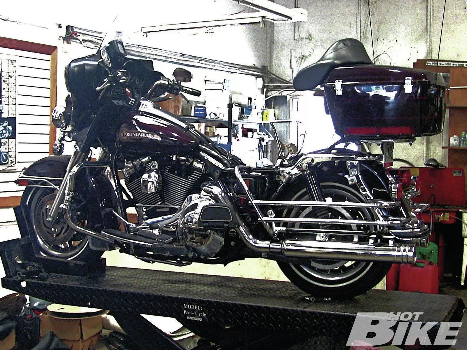
01. The first step in the process was to put the bike on a lift, remove the saddlebags, the seat, and the left side-cover. The battery was also disconnected for safety.
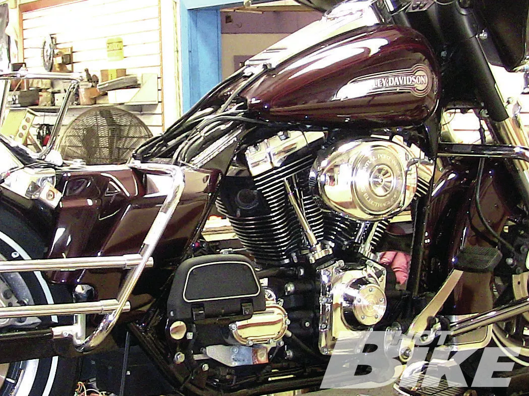
02. The right floorboard and the entire exhaust system was removed to allow access to the lower attachment points for the system which mounts much like a center-stand, below the transmission.
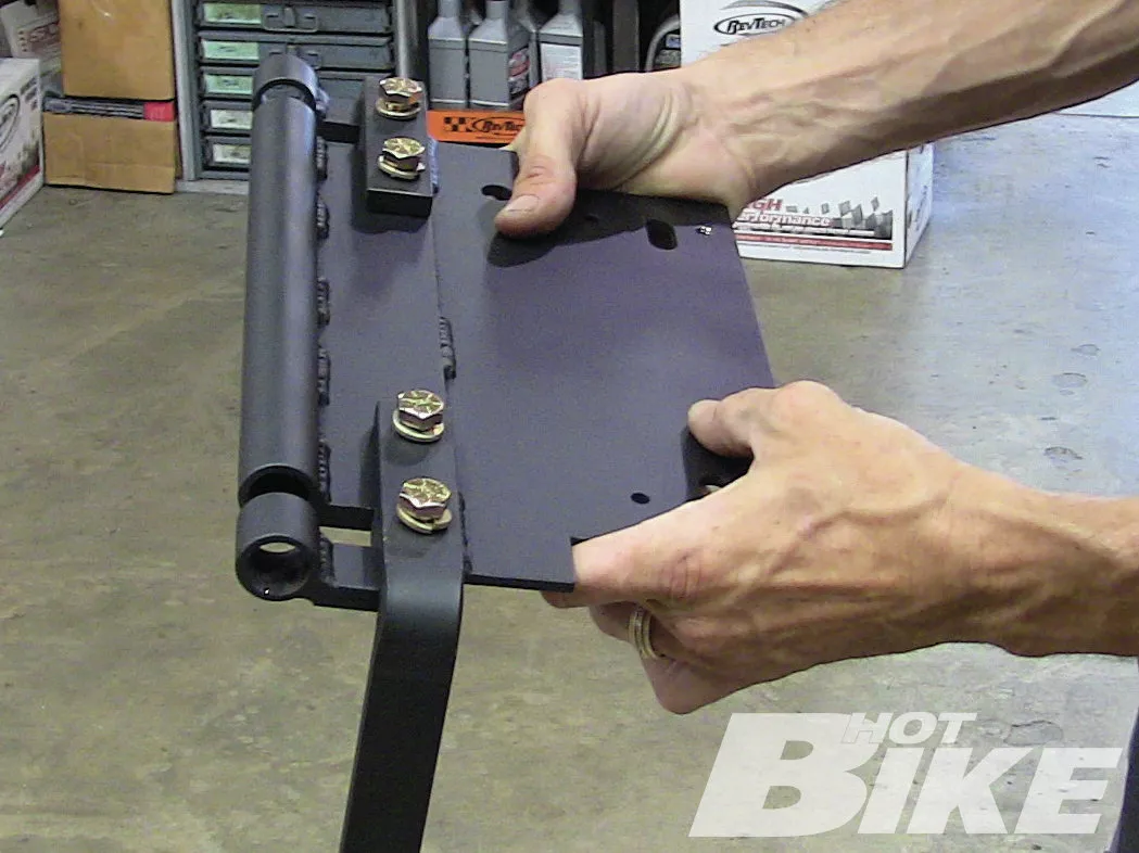
03. This is the lower attachment plate that supports the wheel system. It is made from thick steel offering a stout connection between the wheel system and the motorcycle.
04. The attachment plate was slid between the transmission and the lower cross-brace below it. The two uprights were mounted to the lower pillow block bolts that were removed earlier.
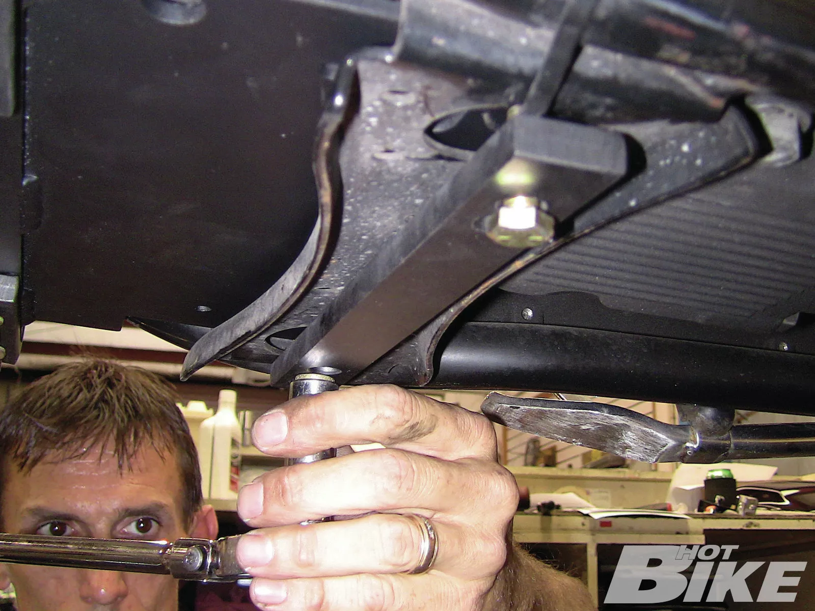
05. This thick strap squeezes the front of the bracket down to the frame’s cross-brace (under the trans pan) to make sure the attachment plate doesn’t pivot under load.
06. The attachment plate was then tightly secured to the lower swingarm pillow block bolt holes with the supplied chrome bolts. This gives the bent steel uprights a rock-solid mount to the bike.
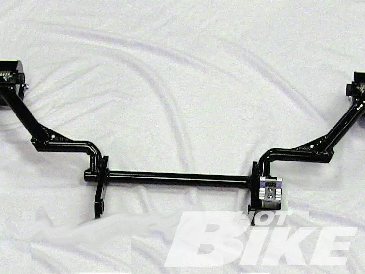
07. The wheel/leg system consists of 3/8-inch steel plate, 7/8-inch solid tubing, and 7/8-inch DOM tubing. The wheels articulate at the end of the legs on an axle with a large spring. This allows some lean angle while the wheels are down permitting low speed turns with confidence. This assembly weighs about 25 pounds. According to Chopper Design Services, it can stand up to the severe stresses placed on it during maneuvers with the wheels lowered.
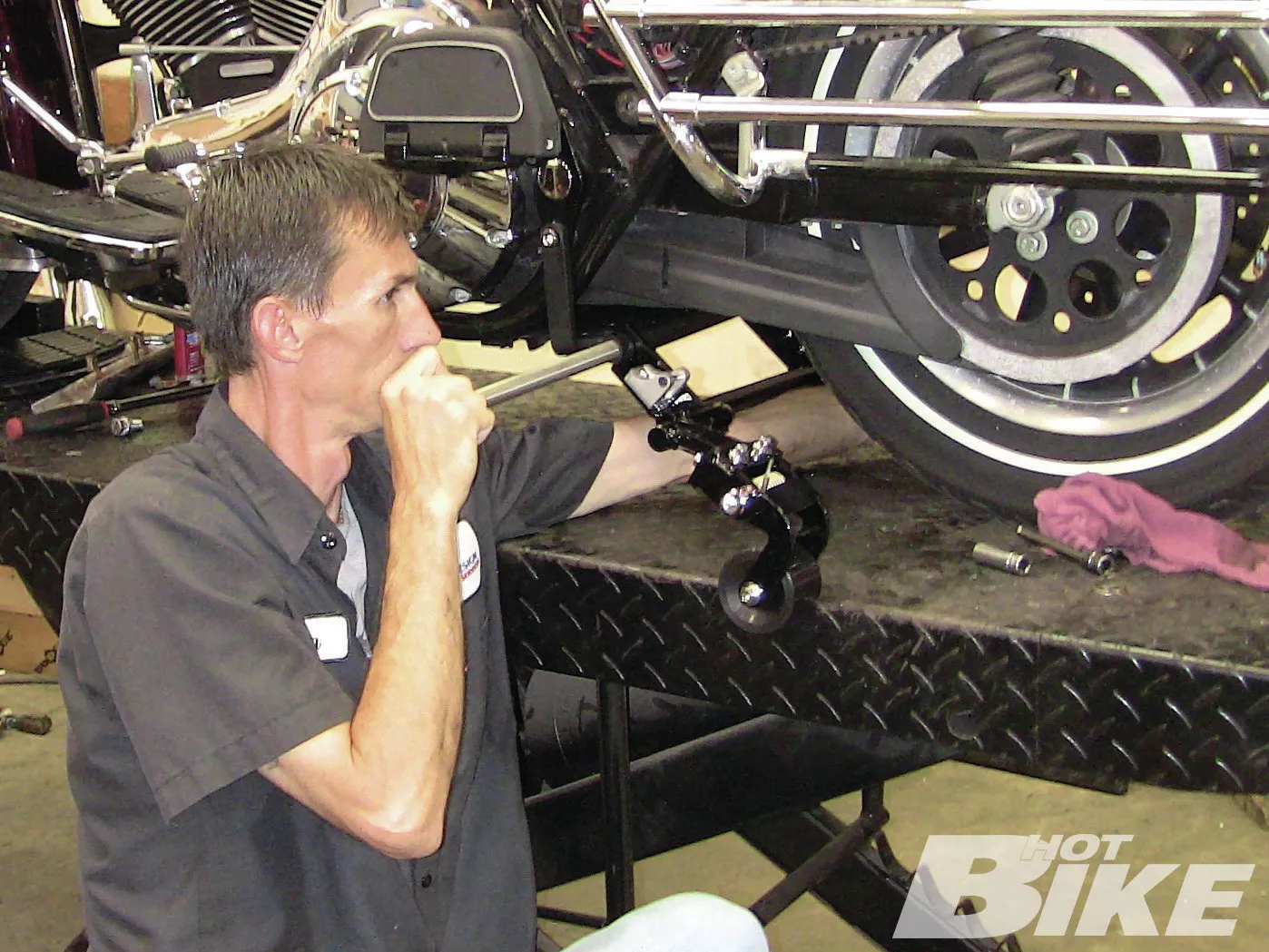
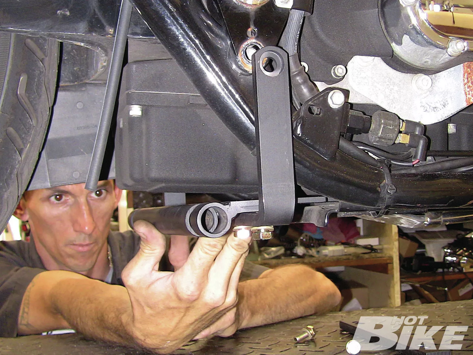
08. The wheel/leg system was slid under the bike and was aligned with slots in the attachment plate that the 3⁄4-inch stainless axle ties together. The axle is being inserted here. The pivot point on the legs uses Oilite bushings, which are basically maintenance-free, and allow smooth pivoting of the wheel/leg system on the axle.
09. Here we see the wheel system installed and the stainless axle capped off. The wheels were then checked to make sure they moved up and down freely and cleared everything under the bike.
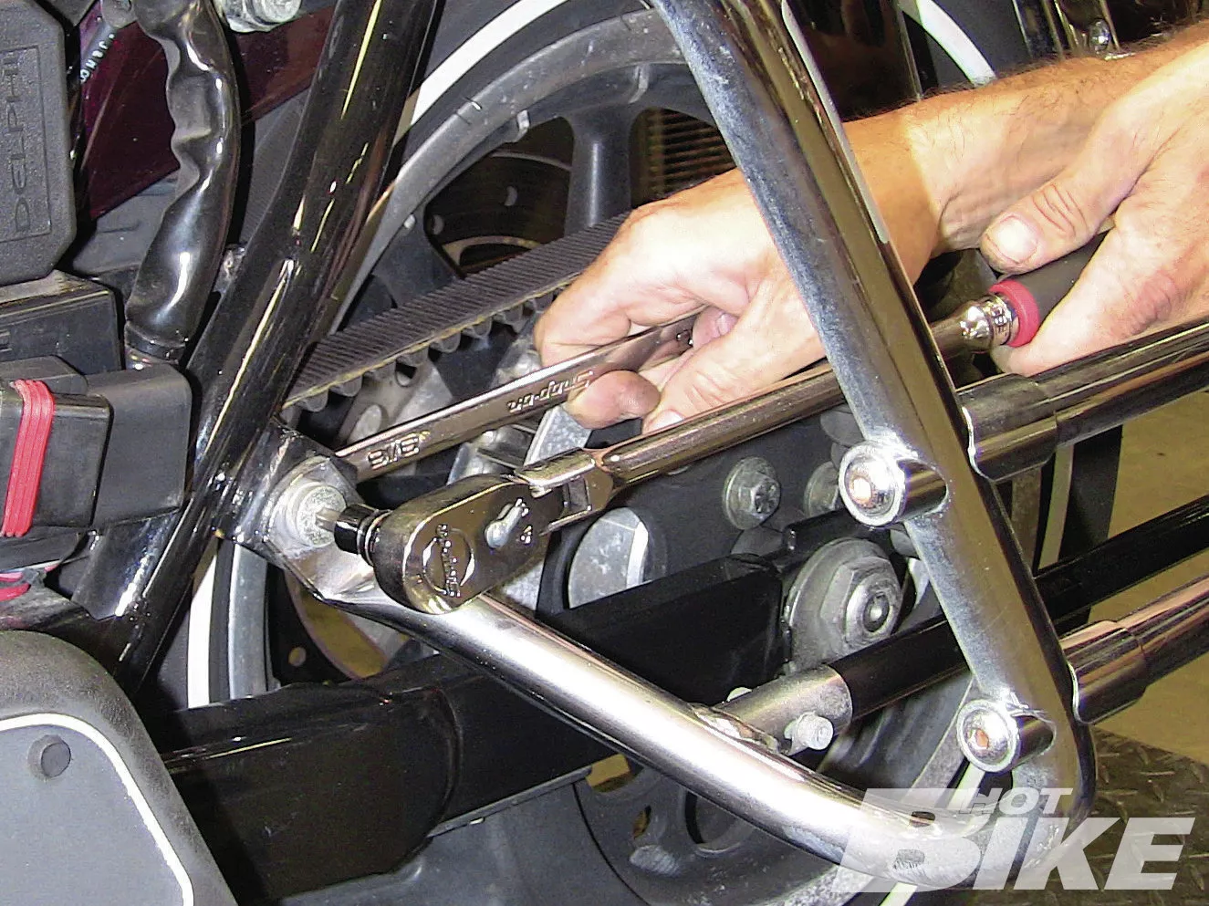
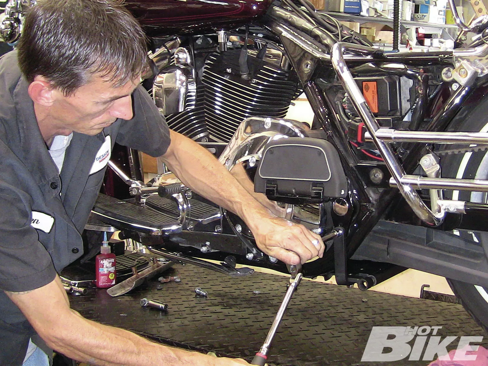
10. Then next step was to mount a bracket that is the upper actuator mounting point. It is captured between the lower saddlebag support on the left side, and the frame tab that the saddlebag support bolts through. The bolt that holds the lower rear crash bar was removed and it will be replaced by the bracket and a new bolt in the next step.
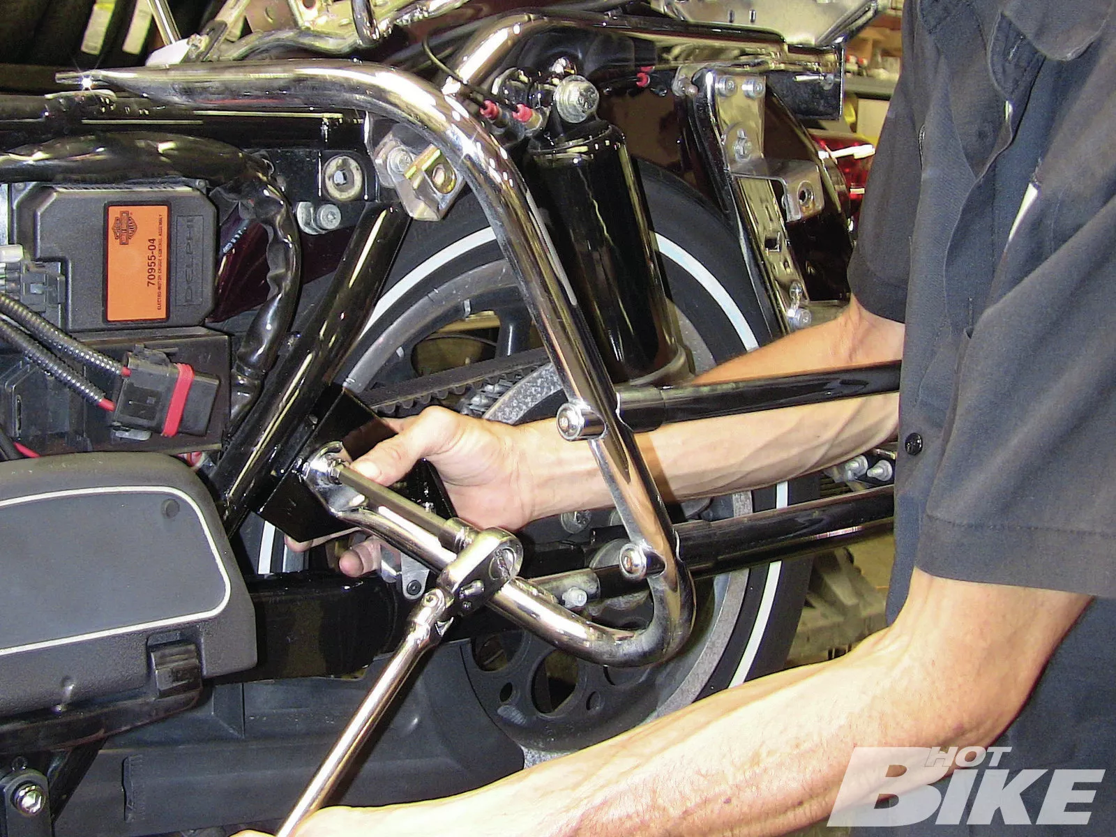
11. Here the upper actuator bracket was captured between the frame and crash bar, it was tightened securely with a new 7/16-inch chrome bolt. Notice the aluminum bracket bolted to the actuator bracket. This assembly holds the axle that the electrical actuator mounts to and pivots on.
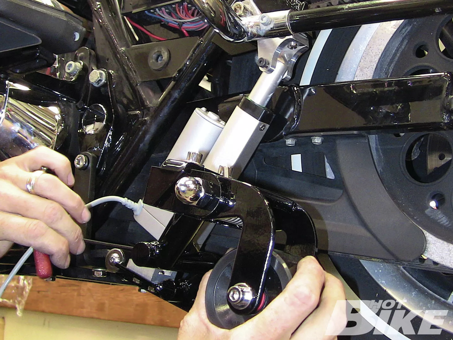
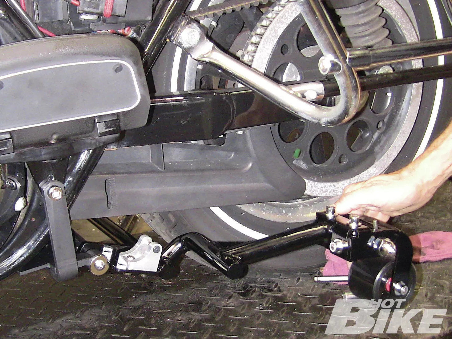
12. Next, the actuator was attached to the leg/wheel system and the upper actuator bracket that was mounted in the previous step. There is adjustment built into the aluminum mounts to allow critical alignment of the actuator. When the exhaust system is reinstalled, this actuator will move in and out between the swingarm and the left exhaust pipe, making the actuator almost invisible.
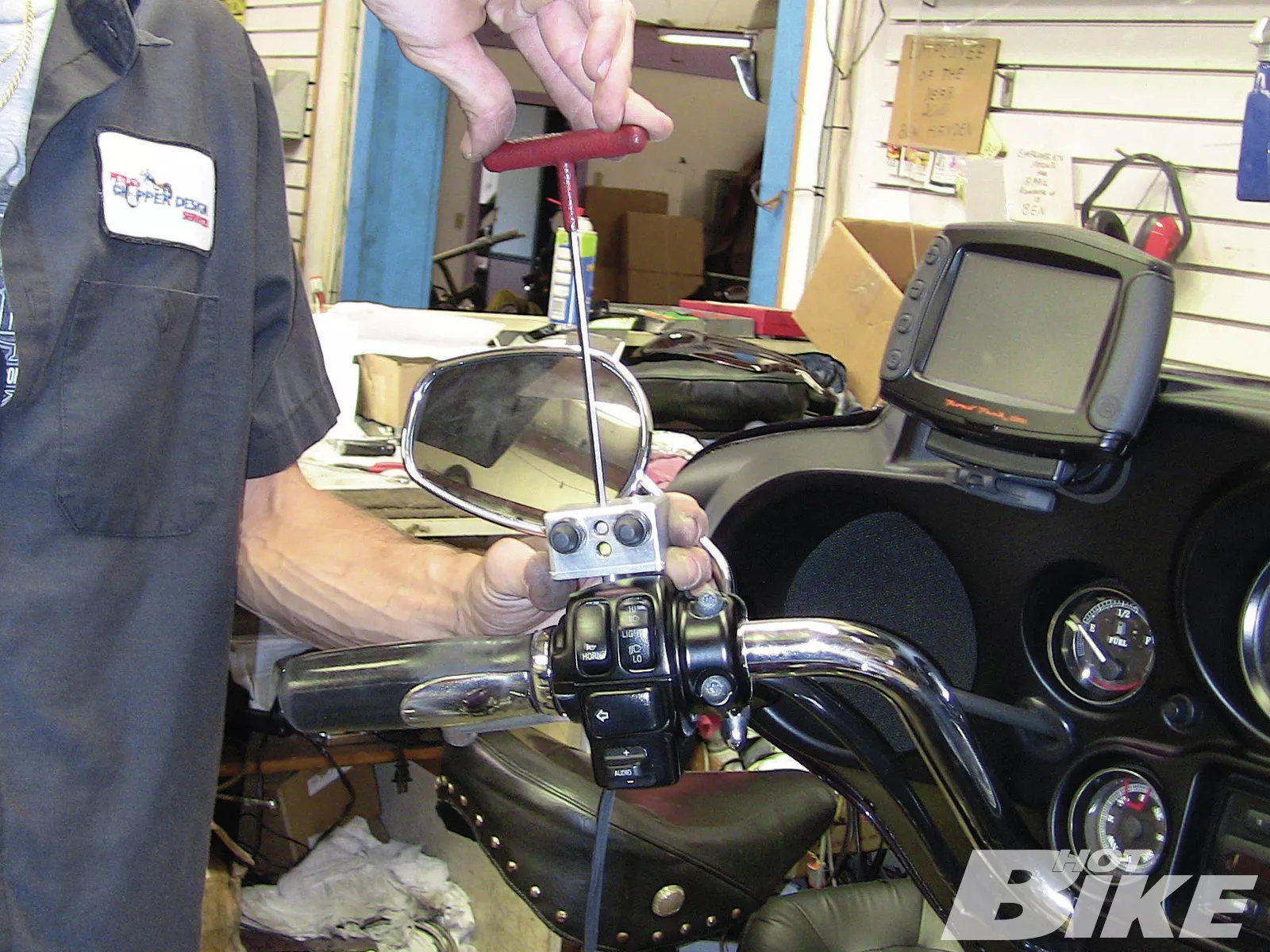
13. The control box seen here has two buttons and two LEDs. It was mounted directly above the left switch housing, making the single button used during a ride easily accessible to the thumb. A no-cut wiring harness was routed from the control box and throughout the bike to attach all the devices and controls.
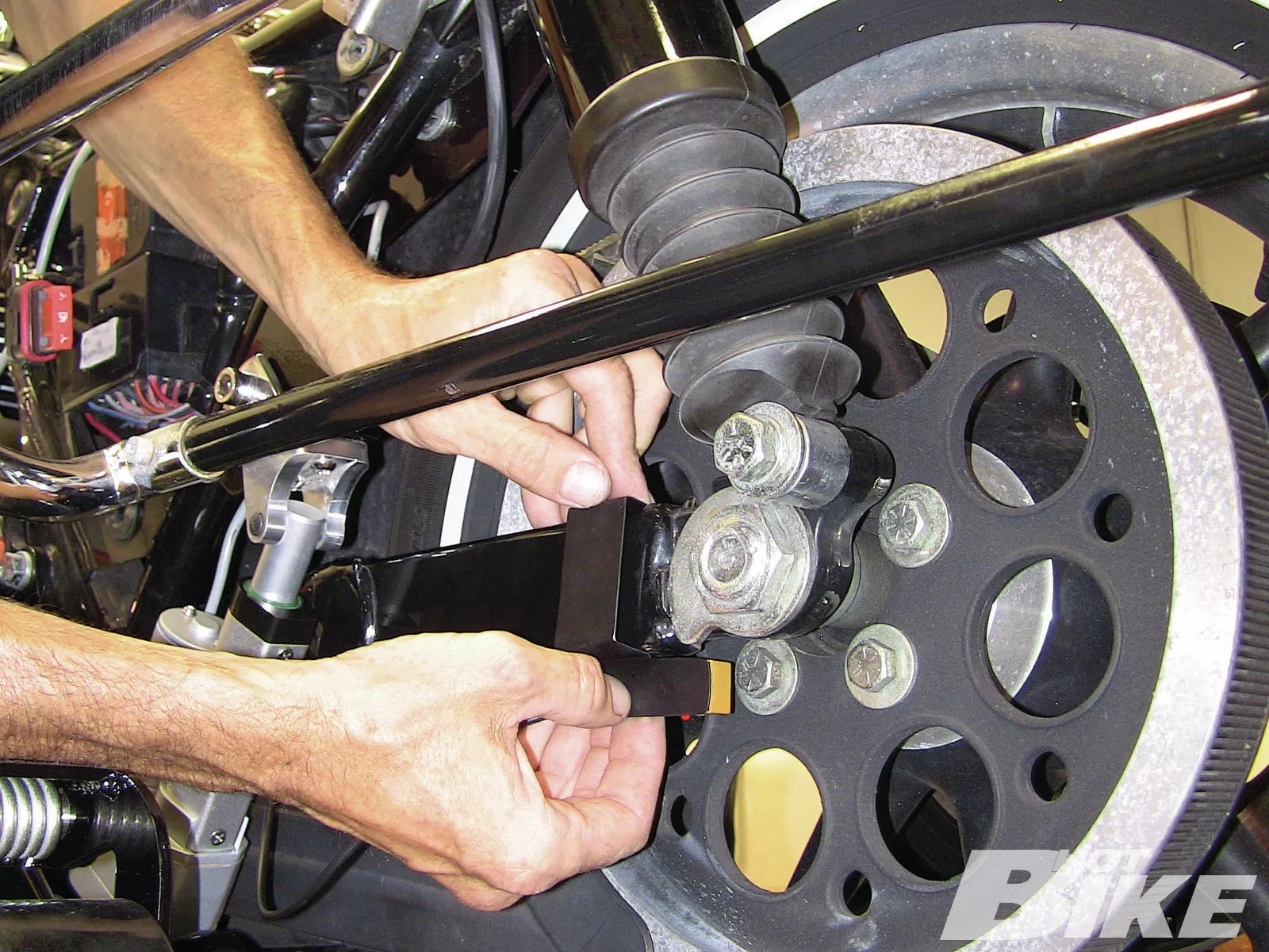
14. The next step was to mount the proximity sensor on the swingarm. This device senses the pulley bolts passing closely by its face, sending a signal to the computer to calculate speed. This sensor can see 4,000 transitions per second; a bit faster than the bike can spin these bolts. Placement is critical here as the sensor must ride no further than 5mm from the pulley bolts. On Cush-Drive models (’07-later), a different bracket is used that tracks the rear rotor bolts since there are no pulley bolts on Cush-Drive bikes.
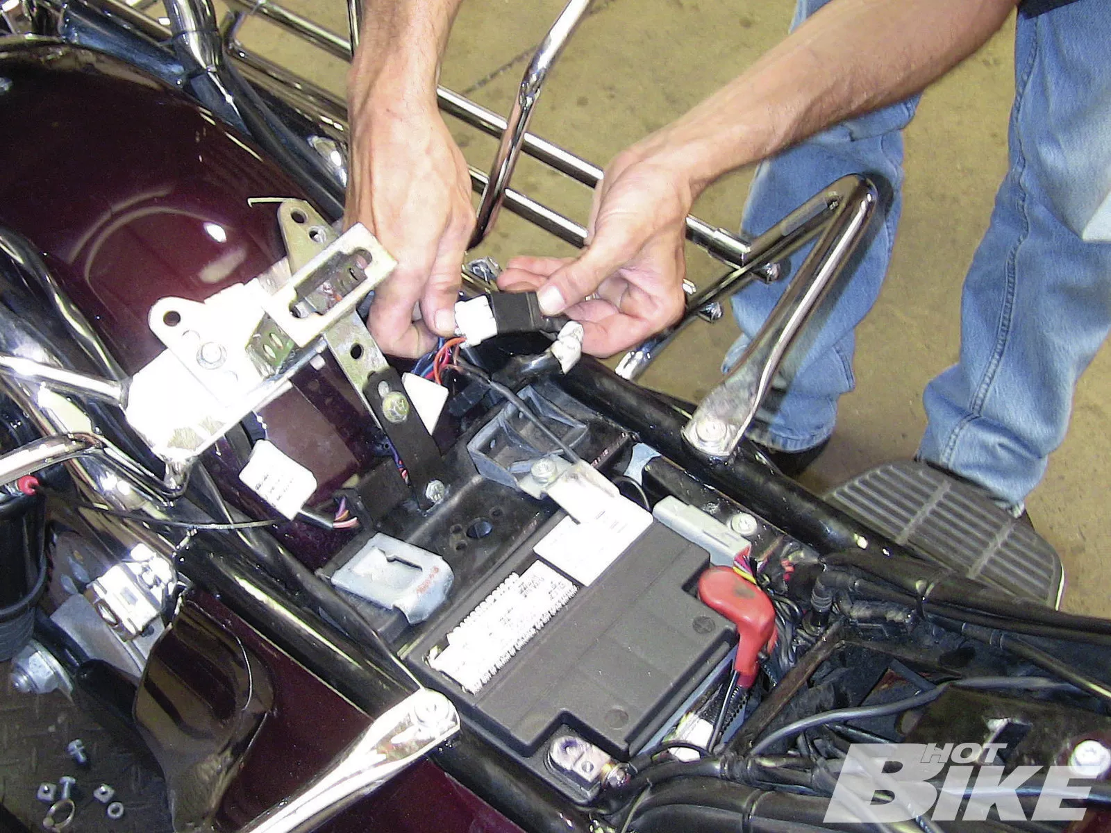
15. Finishing up the wiring harness, the last plug is an in-line affair with the rear fender wiring. No cutting or soldering was involved. The connectors were all tied down neatly and are barely visible.
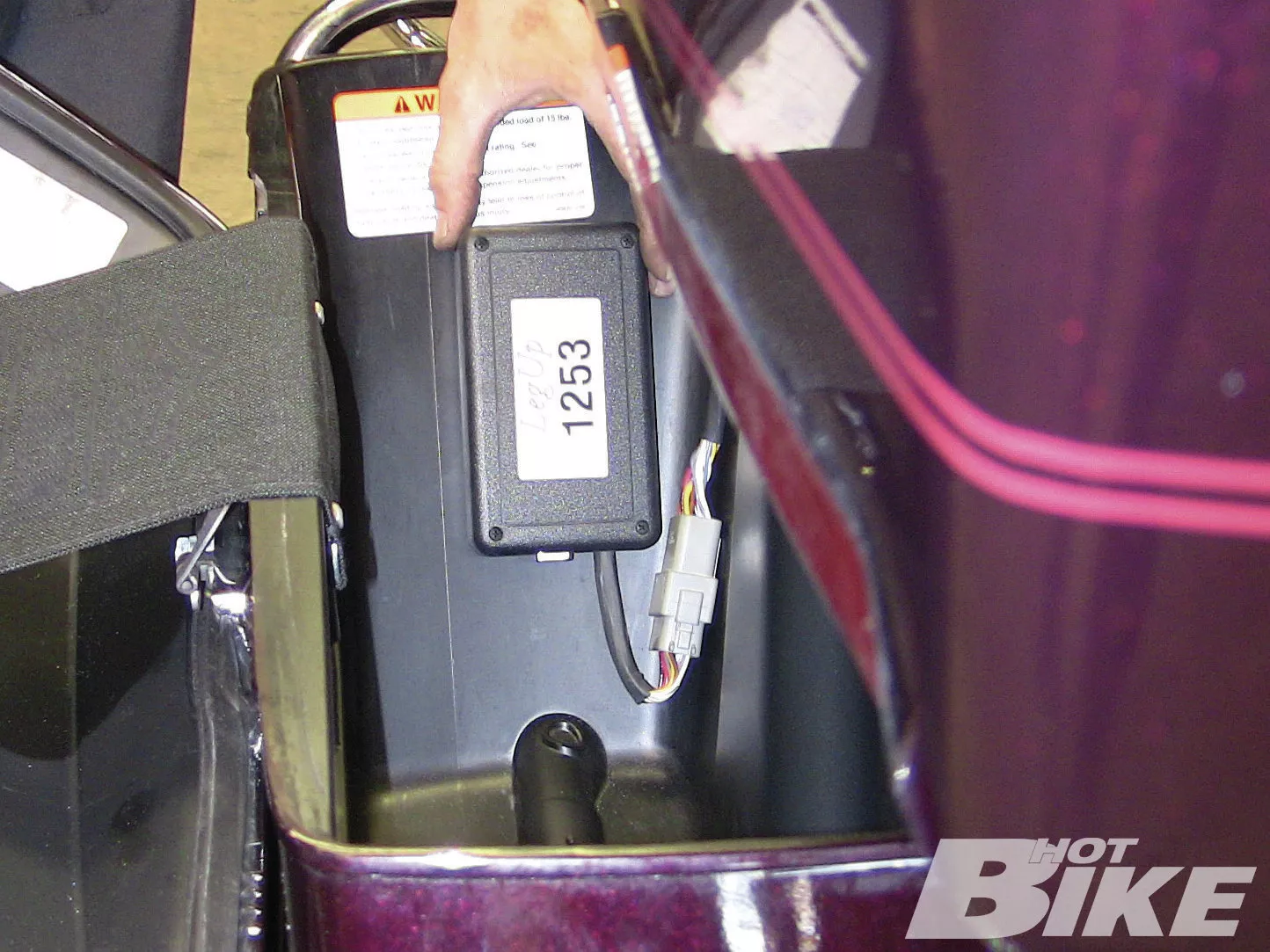
16. Here we can see the small dedicated computer controller mounted inside the left saddlebag. A small notch was made in the saddlebag to allow the wire and plug to fit under the lid without crushing the wire. All plugs on the wiring harness use Deutche connectors that are easy to assemble and disassemble, and are also weatherproof.
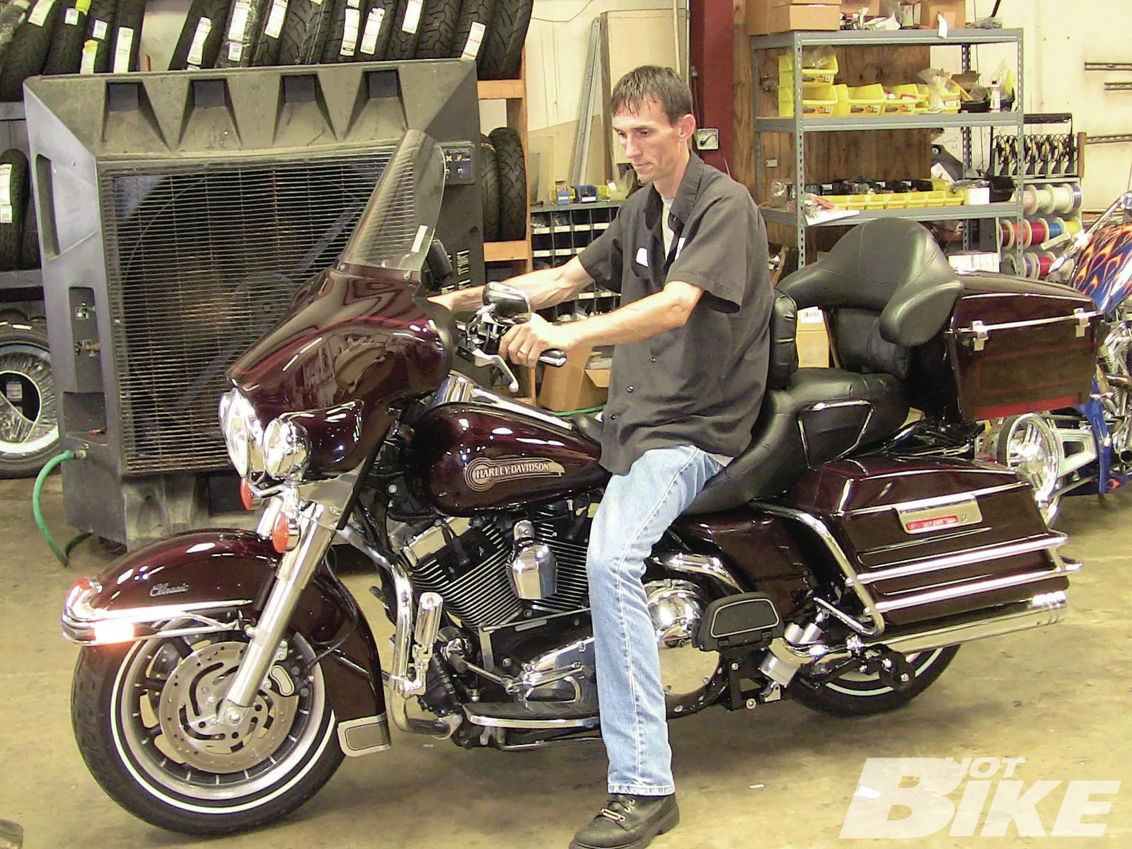
17. The bike was removed from the lift and the system was adjusted. The computer was taught how far down the down-stop should be and how far up the up-stop should be. This allows LegUp to be installed on stock or lowered bikes, and allows adjustment for one-up or two-up, loaded or unloaded conditions. Here the bike has the wheels up. Hard to see them isn’t it?
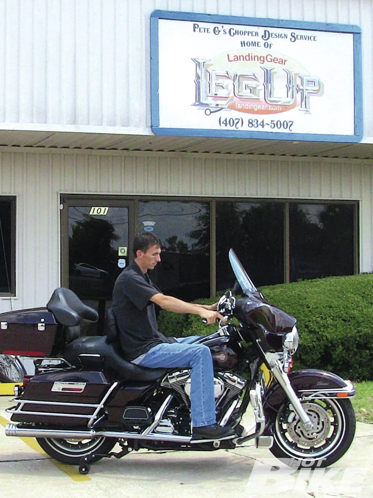
18. Here is a shot of the bike standing on its own with the kickstand up and feet on the floorboards. This makes a big bike feel much lighter. The LegUp system deploys (lowers) the wheels at 9 mph while decelerating, and retracts (raises) them at the same speed under acceleration. The spring-loaded wheels adjust to less-than-level road surfaces and allow the rider to make low speed turns either in a vertical (trike-like) posture or leaning into the turns slightly giving riders a big boost of confidence in the most difficult circumstances they can face on these heavy bikes. To see a video of the system in action, log onto hotbikeweb.com.
Chopper Design Services of Longwood, Florida, manufactures a very unique accessory for touring bikes. The LegUp LandinGear system is aimed at riders with any sort of difficulty keeping their motorcycles upright when coming to a stop or at low speeds due to physical limitations. When riders are considering a trike conversion, LegUp may be the perfect alternative.
The system is a bolt-on, computer-controlled retractable wheel system that automatically lowers as the motorcycle comes to a stop, and automatically retracts upon acceleration. Unlike a trike, this system allows full functionality when the bike is in motion, and even allows leaning of the bike at low speeds with the wheels lowered. The system is barely visible when retracted and even hard to notice when the wheels are down. LegUp essentially makes your kickstand an optional device. LegUp LandinGear is currently available for ’87-10 Harley Touring bikes, as well as Softails and Dynas. We asked Chopper Design to show us how this system is installed on an ’06 FLHTCUI.HB
Source:
Chopper Design Services
(407) 834-5007 | landingear.com


