
Frame Terms
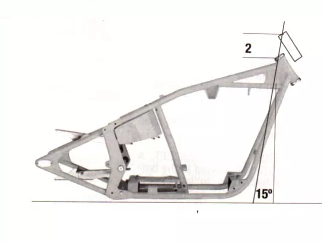
In the case of a 2-inch upward stretch, the steering neck would be raised 2 inches from its stock position. Daytec’s frame jigs are designed with a 15-degree rail used to locate the steering neck. When the shop raises the neck 2 inches, the measurement is taken along this 15-degree angle. This means that 2 inches will need to be added to the bottom rails in order to reach the new position of the steering neck.
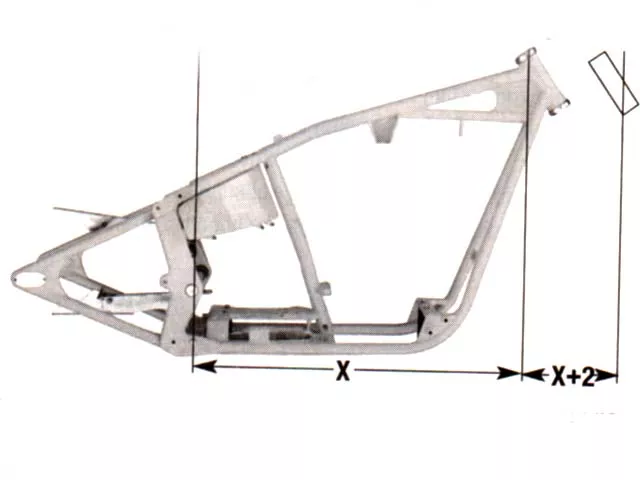
When adding backbone stretch of 2 inches, a measurement is taken from the centerline of the rear axle (in the case of a rigid) or the pivot axle (on a bike with a swingarm). The neck is then moved 2 inches away from and perpendicular to that centerline. Next, calculations are made to determine the length and any bends that may be needed in the new backbone and bottom rails. From there, the frame is welded up in a jig as usual.
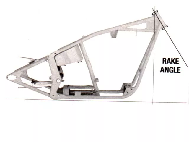
While we’re discussing how to move the steering neck, it would be appropriate to talk about rake angle. Rake is expressed in degrees based on the measurement between the line perpendicular to the bottom rails and the line extended through the axis of the steering neck. As this angle is increased, steering response is slowed down and stability at higher speeds is increased. Conversely, as neck rake is decreased, steering becomes more responsive at lower speeds, but high speed stability is adversely effected.
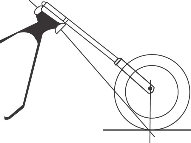
To measure trail, start by holding a tape measure straight up and down from the front axle to the floor. Put a mark on the floor at that point. Then place the tape parallel to the steering axle, following the angle of the steering head all the way down to the floor. Put a mark here, too. Now all you have to do is measure the distance between the two marks, and you have your trail figure. It should read between 2 and 4 inches.
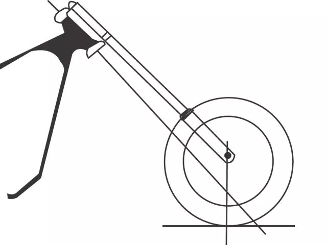
Somewhere between 2 to 4 inches, the bike will handle easily at both high and low speeds, flowing smoothly through curves without swaying or wobbling. If you use a very fat rear tire, you should keep the trail as close to 4 inches as possible. A slightly larger trail is also practical for touring.
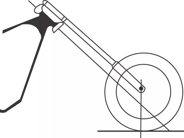
If the trail is more than 4 inches, the bike will handle sluggishly at high speeds. It will seem almost too steady. You will have trouble balancing your bike at lower speeds or on winding roads. It will feel generally sluggish and clumsy.
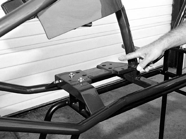
One look at the rear of our rigid, and it’s obvious that there is no suspension present. Once the 250-series tire and wheel is introduced to the rear axle, the air in the tire will be all the cushioning available to the rider.
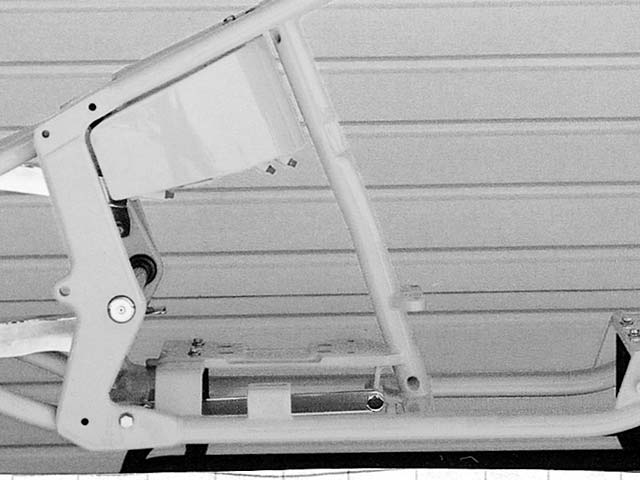
The suspension for a Softail is designed to give the appearance and lines of a rigid frame, while still affording the rider the opportunity of a working suspension. A triangular swingarm is mated to the frame via the solid pivot axle. Smoothing out the bumps are reverse-operation shock absorbers that mount to links on the bottom front of the swingarm and under the transmission mounting plate.
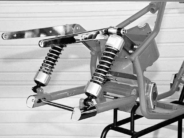
More traditional rear suspension is used on this rubber-mount frame. A beefy 1-1/2-inch single tube swingarm is connected at its foremost point to the frame near the pivot axle. The rear of the swingarm is united with the frame via a set of shocks that spans the gap that are created between the shock towers (2) on the top and the shock mounting lugs (2) on the swingarm.
One very important aspect of any frame is how the motor and transmission are mounted to it. A strong, solid connection between the driveline and the frame ensures a predictable and dependable union of the two. This rigid frame uses a 1/2-inch machined steel plate that is welded to the frame to hold the transmission. The motor mounts are also welded to the frame between the center tube and the downtubes. The top of the motor is then secured to the top motor-mount bracket.
In a Softail frame, the driveline mounting is similar to the rigid. Various motor and transmission combinations are mounted to the frame differently; Evos and Twin Cams are mounted in the same manner as the rigid frame. In the case of the Twin Cam Balanced motor, the motor and transmission are bolted directly together, while the transmission has a machined bore that the pivot axle passes through, linking it to the frame for a strong and stable connection.
The rubber-mount frame (such as Dynas, FXRs, FLHs, and others) uses a completely different method of securing the motor and transmission. The pivot axle passes through the rear of the transmission and uses rubber bushings to isolate it from the frame. The front of the transmission is then bolted to the rear of the motor, and the front of the motor gets secured to a rubber motor mount via a stabilizing link. Another stabilizing link connects the top of the motor to the top motor-mount bracket. These links are used to adjust the driveline’s position in relation to the frame. This type of mount provides the rider with a smooth ride with very little vibration.
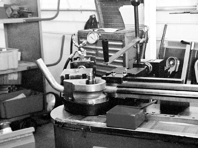
One of the first steps in frame production is bending the tubing to the proper shape. Shown here is a computer-controlled, hydraulically operated bender that produces consistent parts.
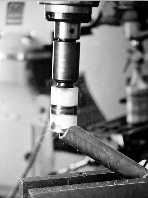
The ends of the tubing must be machined to the proper profile in order to fit tightly to the part it will be mated to.
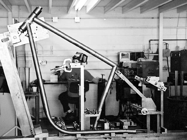
Once all of the tubing has been cut, bent, and prepped with the mounts and brackets machined, it’s time to load the frame jig with the parts. The jig is precision-built from heavy steel in order to accurately hold and locate all the parts so they can be welded. This jig is partially loaded with components.
As they say: “A building is only as good as its foundation.” If you start construction on a foundation that is not sturdy or is poorly designed, you are asking for trouble. The same goes for motorcycles. What is your riding style? Are you looking for form over function? Will this be a daily rider or a bike that does parade duty? These, as well as other questions, must be answered before an intelligent frame decision can be made.
As important as the driveline is for a motorcycle, your first concern should be the frame.
To get a better understanding of what makes a frame, a frame, we went to Daytec Center, located in Hesperia, California, where owner Phil Day brought out three popular frame styles — a rigid, a Softail, and a rubber mount. He then went through each design and explained the differences between them.
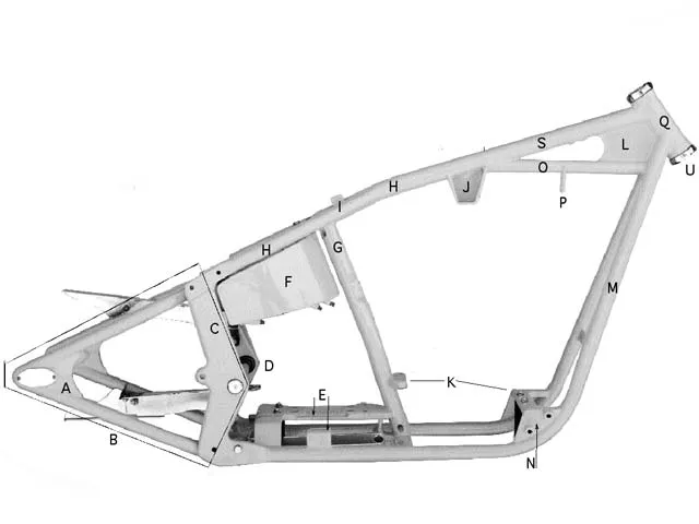
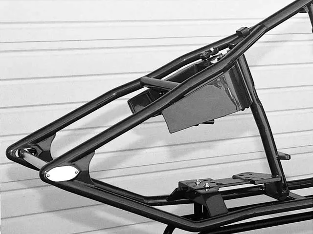
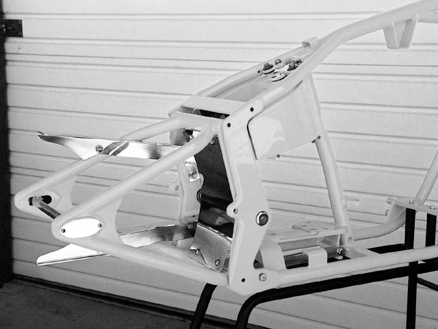
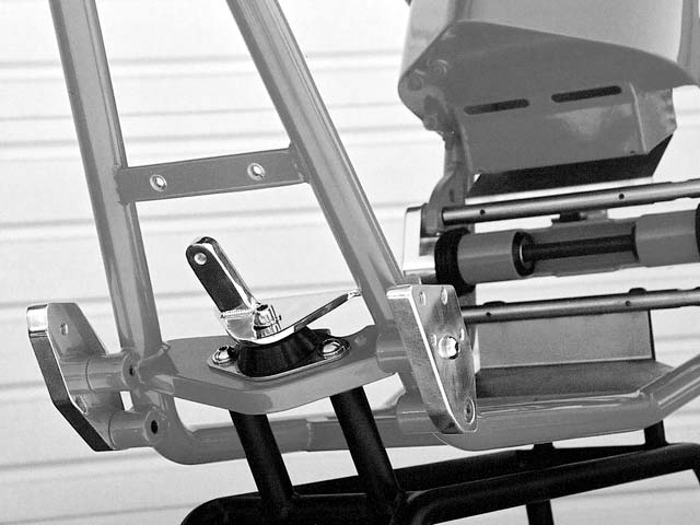
At this point, an explanation of pertinent terms is in order, see figure 1 for reference. A Softail-style frame is used here for illustration purposes only.
PLEASE REFER TO THE IMAGE AT THE TOP FOR THE FOLLOWING DEFINITIONS
A: Hidden axle adjusters: Mild steel plates, machined to accept a rear axle, are adjusted by means of an Allen screw in front of the plate.
B: Swingarm: The rear portion of the frame used to hold the rear wheel in place. The swingarm is attached to the frame by means of the pivot axle. A suspension system bolted between the frame and swingarm is used to cushion and limit the movement of the swingarm.
C: Side Plates: Cold-rolled steel pieces are machined to accurately hold the pivot axle. The plates (there are two of them) are welded to the wishbone tubes on the top and on the bottom rail tubes on the bottom.
D: Pivot Axle: A solid steel, round stock fastens to the side plates and, it provides a pivot point for the swingarm.
E: Transmission Plate: A machined steel plate to which the transmission is bolted. This plate may be bolted to or welded to the frame.
F: Oil Tank/Oil Bag: A sheetmetal tank that holds oil for the engine’s lubrication system.
G: Center Post: A tube welded between the backbone and a crossbrace to add rigidity to the frame.
H: Wish Bone Tubes: Tubes bent to create space for the seating area. They are welded to the top tube in the front and the side plates in the rear.
I: Seat Clip: A small bracket is used to anchor the front of the seat.
J: Top Motor Mount Bracket: A heavy steel bracket welded to the bottom of the backbone, to secure the motor.
K: Motor Mounting Plates: Two steel plates that allow the motor to be bolted to both the front and center of the frame, using a standard engine bolt pattern.
L: Neck Gusset: A flat steel piece is welded to the backbone, neck stem, bottom rails, and neck gusset tube. The neck gusset is used to add strength to this critical area of the frame by spreading the stress and load over a large area.
M: Bottom Rails: Bottom rails (there are two of them) are welded to the neck stem at the front and the side plates at the rear. The vertical portions are sometimes referred to as the downtubes.
N: Forward Control Adaptors: Threaded lugs that are used for mounting the forward controls.
O: Neck Gusset Tube: A frame strengthening member that ties the bottom rails to the backbone.
P: Gas Tank Mounting Plate: A flat steel plate that allows the gas tank to be secured to the frame.
Q: Neck Stem: A machined steel piece that is fit with bearings or bearing cups that will be used to support the frontend.
S: Top Tube/Backbone: A frame member that fits the space between the steering neck and the wishbone tubes.
Stretch and Rake:
Stretch is a word that gets tossed around quite a bit when it comes to custom motorcycles. Although stretching a frame is a very simple concept, it is widely misunderstood.
Simply stated, stretching a motorcycle is changing the length of the backbone and bottom rails (the downtube portion of them) to move the steering neck to a more desirable position.
This repositioning may be done to change the handling characteristics of the motor-cycle, fit the frame to the rider, or more often than not, to give the motorcycle a particular look, i.e. long and low or a high neck.
If a customer orders a frame with 4 inches of backbone stretch, the frame builder will use a longer backbone and modified bottom rails.
There is a common misconception that there are pieces of tube welded into the existing framerails — this is not the case. It is easier and more precise to calculate the new tube lengths and build the frame to its desired dimensions from the start.
Trail
Trail is a measurement of the relationship between neck rake, fork length and style, wheel diameter, and triple trees. This measurement is an important aspect in the handling of a motorcycle. For the type of bikes that we feature on the pages of HOT BIKE, a trail measurement between 2 and 4 inches is the norm.
To measure trail, start by holding a tape measure straight up and down from the front axle to the floor. Put a mark on the floor at that point. Then place the tape parallel to the steering axle, following the angle of the steering head all the way down to the floor. Put a mark here, too. Now all you have to do is measure the distance between the two marks, and you have your trail figure. It should read between 2 and 4 inches. (Note: If your bike is equipped with rear suspension, then have someone sit on the seat when you make these measurements, in order to simulate actual riding conditions).


