Valve Training Part II – Hot Bike Tech
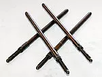
The difference between a good pushrod and a bad one is straightness, strength, weight, length, and the ability to diminish vibration. Shown are Quick-Install pushrods, which are heavier but easier to install than standard adjustable or one-piece units.
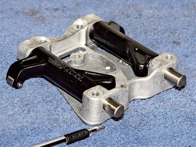
At about 0.550-inch valve lift, consider using forged roller-tipped rockers to reduce valve stem side loading, tip friction, and heat. Beefy rockers made from forged chromoly steel also reduce valvetrain deflection and potential breakage.
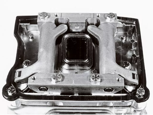
Here’s an example of Baisley Hi-Performance high-ratio 1.7:1 roller rocker arms fitted to Baisley custom Evo rocker stands, circa 1995. The stands are super rigid and provide correct rocker arm geometry with long-stemmed valves and modified valve angles.
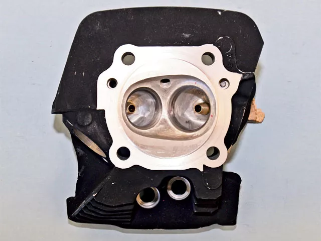
Do not intentionally sink a valve into the seat to adjust valve geometry because this can shroud airflow. If necessary, use a longer stem valve. Long-lasting manganese bronze guides allow tighter valve clearance for better heat dissipation and longer life. – Courtesy Short Block Charlie
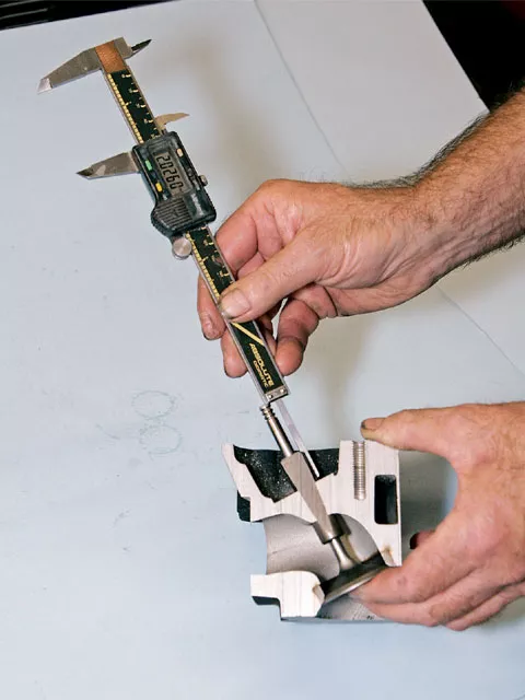
Proper valve-stem height is critical for correct valvetrain geometry. High-lift cams may require the installation of long-stem valves to achieve correct spring spacing between the collars.
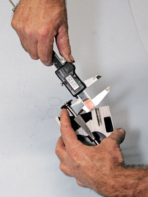
Clearance between the valve collar and guide or valve stem oil seal must be checked with high-lift cams. Valve lift plus .060-inch should be the minimum.
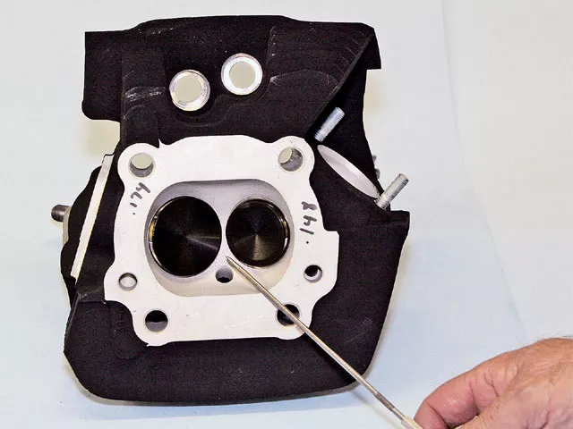
If you installed new valve seats, large valves, or a performance cam, valve-to-valve clearance must be checked. Valves should have a minimum of .060-inch clearance when positioned at TDC lift as specified by the cam instructions.
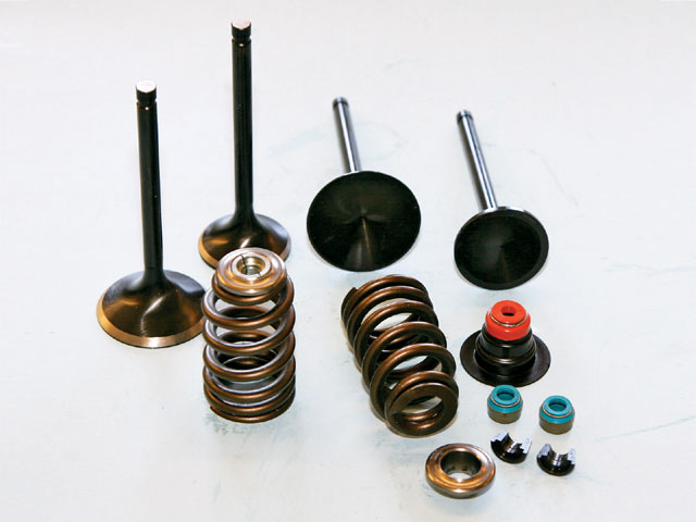
Here are stock TC beehive valve springs and top collars, along with aftermarket valves. Shown in the bottom right corner is a stock late-model TC bottom valve collar with integrated valve stem oil seal. Directly in front are two aftermarket Viton stem seals, which provide maximum valve oil control with a quality spring-loaded wiper, thus preventing unwanted oil from contaminating the cylinder’s airflow.
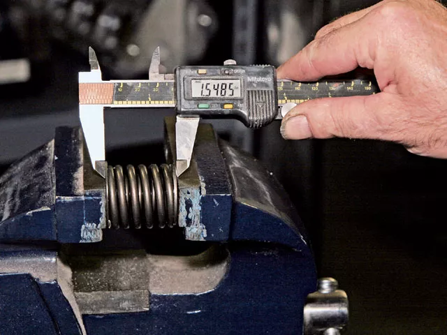
Measuring the difference between the compressed spring height and installed height calculates the maximum valve lift the spring can handle. For clearance and potential valve float, add an extra .060-inch to valve lift.
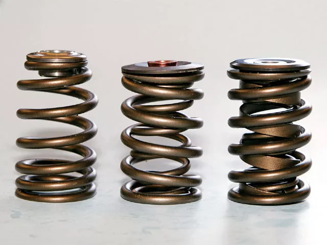
Shown is a progressively wound beehive valve spring on the left, traditional dual coil spring in the middle, and triple spring (dual coil and damper) on right. The conical beehive spring is smaller on the top, allowing the use of a smaller and lighter collar. Reducing mass and weight at the spring’s top is most important because the top moves the fastest and farthest during valve lift.
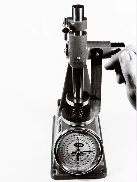
The only way to know for sure what a spring’s exact pressure is at a given installed height is to check it with a valve spring tester. Any spring more than five percent under specifications should be replaced.
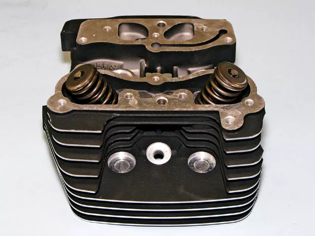
Ideally, what you want from a spring is low mass, sufficient spring force, and long fatigue life. The stock beehive spring package in this assembled TC head was replaced with traditional dual coil springs, titanium collars, and Viton valve stem seals to match the specific requirements of a performance cam.
Last month in our Motor Series article, we covered the importance of making the valve do what you want it to do and engineering the entire valvetrain as an integral package. We then went on to cover the camshaft drive mechanism and lifters. This month we will pick up with pushrods and work our way up through the valvetrain.
PushrodsThe pushrod looks like a rather simple part that connects the lifter to the rocker arm. However, the difference between a good pushrod and a bad one is straightness, strength, weight, length, and the ability to diminish vibration. Pushrods must withstand two fundamental forces: compression and deflection. Pushrods deflect under high loads due to the angularity between the lifters and the rocker arms. Oblique angles enhance side loading, which leads to deflection if the pushrod is not rigid enough. Once the pushrod deflects, it retards valve timing while reducing net valve lift, valve duration, and airflow. The result is reduced cylinder filling and power production.
The Twin Cam, Evo, and Shovel Big Twin engines have relatively poor valvetrain geometry due to the extreme angularity of their pushrods. Additionally, very large-bore Evo and Shovel Big Twin engines often have the camshaft offset to the right side, compounding the geometry problem. Poor geometry reduces performance and durability. The V-Twin’s front exhaust pushrod is angled the greatest amount, resulting in the worst geometry of all the valves. The more in-line the pushrod is in relationship to the lifter axis, the better the geometry. The Twin Cam’s dual cams reduce pushrod angularity slightly, thereby offering a geometry improvement over the Evo and Shovel engines. However, the Sportster has the straightest geometry due to its four-cam design. With this design, each cam can be placed under a rocker arm, reducing angularity. This is the reason some engine builders use a four-cam Sportster-style crankcase for racing.
Twin Cam and Evolution engines use hollow steel one-piece non-adjustable pushrods, while Shovelheads shipped with solid aluminum adjustables. By design, TC and Evo pushrods not only transmit motion to the rocker arm assembly but also supply oil to the top end through a hollow interior. Various length pushrods are required for each pushrod position due to the different angles leading to the rocker arms. The Twin Cam engine uses a different one-piece length pushrod for intakes and exhausts, while the Evo and Shovel use four different length pushrods. The correct pushrod length must be used in each valve position to help maintain correct valvetrain geometry and adjustment. Stock length pushrods will work properly as long as the cam’s base circle is the same diameter as the stock cam and stock length cylinders are used. Although long pushrods are required when extra-long cylinders are installed, it is best to keep pushrod length to a minimum.
Performance V-Twin pushrods are available in three major styles: EZ-Install adjustables, standard adjustables, and one-piece non-adjustables. The EZ-install units are usually heavier but allow for easier installation and adjustment, saving time and labor costs. In contrast, standard adjustable units are lighter but usually require additional work for installation. One-piece high-performance pushrods (not stock) are lighter than adjustables, but are sized for a specific engine combination and require additional work for installation.
Stock Twin Cam one-piece pushrods are impractical to use with high-performance cams. These pushrods should be replaced with either aluminum or heat-treated 4130 chromoly units. Aluminum pushrods are lighter while chromoly units have more rigidity. Aluminum flexes about three times as much as chromoly when under high load. When pushrod flex is combined with hydraulic lifters, lifter pump-up often occurs, resulting in loss of valve control. Reducing valvetrain weight is always a goal when building a performance engine. However, when trading off less weight for rigidity, rigidity wins every time. Accurate valve timing is much more important than reduced weight. Overall, you’re much better off with chromoly pushrods, although they are noisier than aluminum when used with solid lifters.
The larger the pushrod’s outside diameter (O.D.), the thinner walled it can be for a given amount of strength. Depending on the material and the manufacturer, most aftermarket pushrods vary between 3/8-inch and 7/16-inch O.D. and .049-inch and .095-inch wall thickness. Higher valve-open spring pressures, higher engine rpm, higher rocker arm ratios, increased valvetrain acceleration rates, and greater angularity between the lifter and rocker require a stronger pushrod. Long pushrods and high valve spring pressure require a stronger pushrod tube. As tube strength goes up, so does weight. Consequently, higher valve spring pressures are required.
It is suggested to use the largest diameter, stiffest, and strongest pushrod that will fit into the engine to minimized deflection, but keep in mind that this will also increase the chance the pushrod will rub against another engine part. Deflection can also be minimized by using single- or dual-taper pushrods. Tapered pushrods help dampen harmonics in the valvetrain, extending valve spring life while increasing usable rpm. Tapered pushrods also reduce valvetrain harmonics while providing maximum strength with minimum weight.
For maximum performance, pushrods must be perfectly straight. If a pushrod is bent, it is either too weak for the valve spring pressure or there is interference such as coil bind somewhere in the valvetrain. The best way to check a pushrod for straightness is to roll it across a perfectly flat surface such as a piece of glass.
Rocker ArmsThe V-Twin engine uses four Z-shaped rocker arms that not only actuate the valves but also can be used as a valvetrain tuning tool. Stock rockers have a radiused pad that contacts the valve stem. This design works well, but if used for lifting valves more than 0.525- to 0.550-inch, it will cause accelerated valve stem and guide wear. At about 0.550-inch valve lift, consider installing forged roller-tipped rockers to reduce valve stem side loading, tip friction, and heat. Beefy rockers made from forged chromoly steel also help reduce valvetrain deflection and potential breakage. The increased beefiness of roller rockers usually requires clearancing the rocker covers. But don’t modify or lighten the rocker arms, because the V-Twin rocker’s long tube and lever design already lacks optimum stiffness.
The nominal rocker arm ratio for Twin Cam and Evolution engines is 1.625:1 (1.43:1 for the Shovelhead and Ironhead Sporty). That means for every 0.100-inch of lifter lift, the valve will theoretically move 0.1625 inches. However, in reality the valve will move less due to deflection of valvetrain components. Take note that there is a critical difference between lifter lift (cam lift) and valve lift. High ratio rockers are available to increase valve lift without increasing cam lift. With a high-ratio 1.7:1 rocker, for every 0.100-inch of lifter lift, the valve will move 0.170 inches instead of the 0.1625 inches with a stock rocker. That means a cam designed for 0.500-inch lift and stock 1.625-ratio rocker will lift the valve 0.523 inches with a 1.7 rocker. Although stock rockers are rated with a 1.625 ratio, this is seldom the case. In most situations, the ratio varies and is slightly less, which is another reason to opt for quality high-performance rocker arms.
Now that you know the basics of rocker arm ratios, here are some subtle tuning points that often go unrealized. A higher rocker arm ratio will lift the valve faster and farther for a given camshaft profile. A larger ratio will make a cam appear more radical to the engine while a smaller ratio makes it appear milder. A higher ratio rocker will also make the engine’s power peak occur at a higher rpm. Besides lift, rocker ratio also affects cam duration. The greater the rocker arm ratio, the longer duration will be when measured at the valve. It will also close the valve later than a lower ratio. As a result, increasing the rocker arm ratio increases camshaft duration at the valve because the time (as measured in crankshaft degrees at .053-inch) the valve is open beyond .053-inch increases.
Keep in mind, however, that high-ratio rocker arms are not always the better setup. For example, it is possible to over-scavenge a cylinder, thereby tossing horsepower out the exhaust with the same result as if you ran too radical of a cam for the engine combination. Knowledgeable engine builders use high-ratio rockers as a tuning device to compensate for a weak-flowing cylinder head port or for determining whether an engine can benefit from more or less cam on the intake and exhaust sides. When changing rocker ratios, the ratios can be identical for both the intake and exhaust sides or biased toward one side or the other. If biased, you’ll often find the ratios greater on the intake side. Ratios can also be different between each cylinder to provide multiple torque and horsepower peaks or compensate for airflow deficiencies.
Valvetrain GeometryValvetrain geometry is critical for maximum performance and reliability, and understanding it will give you a performance advantage. To minimize valvetrain stress and optimize valve lift and duration, the angles between the pushrod-and-rocker and rocker-and-valve stem should be 90 degrees when the valve reaches 50 percent of its maximum lift. This relationship applies to both radiused-pad and roller-tipped rockers. The angle between the axis of the rocker arm (when measured from the center line of the rocker shaft to either the radiused pad or roller tip axle centerline) and the end of the valve stem should be less than 90 degrees when the valve is fully closed. At maximum lift, the angle should be greater than 90 degrees. Optimizing rocker arm geometry minimizes valve side loading and optimizes valve timing since the rocker applies pressure equally to the valve stem. It also lifts the valve to its maximum potential.
A few things can be done to correct inaccurate rocker arm geometry. First, the valve stem height can be adjusted. When the valve is sunken into its seat, the valve stem sits higher in relationship to the rocker arm. However, it is not recommended to intentionally sink a valve because this often shrouds it. With a large valve installed, it is possible for the valve stem to sit lower than its normal position. Incorrect geometry can sometimes be corrected by installing new valve seats. Other times, valves with extra-long stems are required, or the cylinder head’s rocker-arm stand mounting pad can be machined or shimmed. High lift cams may also require the installation of long valves to achieve correct spring spacing between the collars.
Valvetrain geometry will also affect where the rocker arm’s radiused pad or roller tip contacts the valve stem. The rocker arm’s point of contact with the valve stem moves back and forth as the valve moves up and down. At zero lift, the rocker arms contact point should be slightly toward the rocker side of the valve stem. This will allow the rocker to sweep back and forth, equally against the valve stem, reducing side loading and wear. The radius pad on solid-tipped rockers can be refinished (with the correct radius) to adjust the valve stem contact point. Valvetrain geometry should be checked at the same time the heads and valves are setup.
Springs, Collars, And KeepersThe most critical component of the valvetrain is the valve spring. Most performance cams lift the valves higher and accelerate more quickly than a stock cam. This requires higher valve spring pressure to eliminate “valve float.” Valve float is the condition where the valve loses contact with the valvetrain due to high inertia and the valve stays open when it should be closing. Float can lead to valve and seat damage. Heavy valvetrain components, low valve spring pressure, and high rpm are the major causes of valve float. The common solution for valve float has been to increase spring pressure. But there is a delicate balance between too much and just the right amount of spring pressure. Increasing spring pressure increases stress, heat, and fatigue, and can cause the spring to lose tension quickly.
Ideally, what you want from a spring is low mass, sufficient spring force, and long fatigue life. These characteristics will result in a spring with long life and high resonant frequency. Springs with a higher resonant frequency are more resistant to surge (spring harmonics), which should not be confused with valve float. All valve springs resonate at a given frequency and reach that frequency at a given rpm. The resonance is a function of both a spring’s rate and its mass. When a spring resonates or surges, it loses the ability to control its own mass. This results in the spring’s delivered pressure fluctuating widely; essentially the spring loses the ability to close the valve and hold it closed, which causes a power loss at whatever rpm the surge occurs. One method for controlling surge is to use dual oppositely wound interference-fit springs. Sometimes a flat-wound damper is added as a third coil.
When selecting a spring, look for one wound from high-quality wire and with sufficient spring pressure for the application-weight of the valvetrain components, aggressiveness of the cam profile, and engine rpm. High-quality wire is freer from metal impurities, which are a major source of spring failures. If two springs deliver the same seat and open pressure, the lighter weight spring will control the valvetrain better. Therefore, always factor spring weight into the selection criteria.
Dual and triple valve spring combinations have been around for a long time. To combat resonance, decades ago Detroit automakers resurrected research on a spring design known as the “beehive” spring. The beehive spring’s conical shape results in a lower mass at the collar area, thus allowing for better valve control in certain applications. Today, beehive springs are used in many automotive and high-performance applications. Beehive springs are now used in late-model Sportsters and recently appeared in the Twin Cam engine. Refer to “The Buzz about Beehive Valve Springs” Sidebar on page 78 for additional information.
Valve spring pressure is normally checked when the valve is seated and when it is at maximum lift. Although high spring pressure at maximum valve lift catches everyone’s attention, keep in mind it is seat pressure that closes the valve. The shape of the cam lobe, weight of the valvetrain, and maximum rpm determine the required spring pressure. Running excessive spring pressure increases friction and heat while reducing horsepower. However, from a reliability standpoint, too little spring pressure is worse than too much. Remember that spring pressure will drop after even a short run-in, so watch it closely on a serious race engine. It’s typical to lose 10 or 15 pounds of spring pressure after the initial run-in. This means that if you’re shooting for 170 pounds seat pressure, you may need 185 pounds at installation time.
The only way to know for sure what a spring’s exact pressure is at a given installed height is to check it with a valve spring tester. Any spring more than five percent under specifications should be replaced. Furthermore, check each used spring for proper free length by placing it on a flat surface next to a new one. Any used spring that measures 1/16-inch shorter than a new one is probably fatigued and usually down in pressure. A spring must sit perpendicular against the spring collar, otherwise excessive wear and heat will be generated. Inspect both ends of every spring with a machinist square for correct squareness. Some engine builders pre-condition new springs before installation. The procedure involves placing a spring in a soft-jaw vise and gently compressing it several times without coil binding it. But be careful; you can easily ruin a spring if you’re not careful.
Valve spring kits for the V-Twin are available in various spring pressures and designs, which can simplify cam installation. Some kits include a single coil beehive spring but most use round wire dual-interference fit springs. A few kits include a third spring or flat-wire damper. The interference fit between the oppositely wound springs is designed to reduce harmonics and control spring surge. The third spring will be made of either round or flat wire and will add a slight amount of pressure. If it is made from flat wire, it is designed primarily to dampen natural spring frequencies and reduce spring surge, which quickly fatigues a spring. Better springs are frequently made from chrome silicon wire. When selecting a spring, consider both the weight of the spring and the delivered force.
Spring collars (retainers) and keepers (locks) perform a simple yet tough job. What you want is a stiff collar that will not warp. Collars must also fit securely on the springs and be as lightweight as possible, consistent with the application. Top and bottom spring collars are available in aluminum, chrome-moly, and titanium. Aluminum collars are the lightest, while chromoly collars are the strongest; however, titanium collars offer the best combination of strength and lightness. Some valve collars are machined for additional spring travel, which can ease installation. Bottom collars are designed to fit either “shoulder” or “shoulderless” valve guides. Late-model Twin Cam bottom collars are integrated into the valve oil seal. Machined, heat-treated chromoly valve keys cost more than plain steel stamped units, but they’re the safest way to hold together a high revving engine and are recommended for use on all engines.
Final ThoughtsRemember, the valve must do what you want it to do, and this requires that the entire valvetrain be engineered as an integral package, starting with the camshaft drive mechanism. The valve spring is the most critical component of the valvetrain and must be matched to the cam, valvetrain weight, and rpm. Rigidity is crucial if the valvetrain is to accurately transmit cam lobe action to the valve. Stiffer takes priority over lighter for rockers and pushrods. Reducing valvetrain weight on the valve side of the rocker fulcrum is important because velocities are highest there. Also, reducing valve-side weight will allow a higher rpm for a given valve spring or less spring pressure for a given rpm. Proper valvetrain geometry will reduce parts wear while optimizing valvetrain timing and performance. Use rocker arm ratios as a tuning device and maintain sufficient oil psi for hydraulic lifters. At the end of the day, compromises are unavoidable and durability trumps lightweight parts, because trailering home is no fun.
The Buzz about Beehive Valve SpringsRevving an engine higher, quicker, and longer without self-destructing generally requires heavier, beefier valvetrain parts and higher valve spring pressures. But stouter spring pressures require stiffer springs, increasing weight and system mass. Yet one of the spring’s greatest enemies is the weight it has to overcome to close the valve. Enter the “beehive” valve spring. Although the beehive spring has been around for a long time, it most recently appeared in GM’s Gen III engines. The Factory then followed suit, first introducing the beehive spring in the Sportster and most recently the Twin Cam.
The concept behind the beehive spring is to reduce the mass of the spring itself so the spring will require less seat and open pressure to control any specific cam profile because it will have less of its own weight to overcome. The beehive’s conical shape is smaller on both ends, but much smaller on the top than on the bottom. This shape reduces mass and weight while using a significantly smaller and lighter collar. Since the top half of the spring moves the most during valve lift, cutting mass and weight here is more important than cutting weight at the bottom of the spring.
Beehive springs are wound from ovate-shaped wire, which reduces dynamic stresses the spring experiences during the lift cycle and improves fatigue life. Beehives also dissipate heat more readily than a conventional round-wire spring. Harmonics are always a major concern with traditional cylindrical springs designed with a consistent top to bottom diameter. The combination of progressively wound beehive design and ovate wire increase the spring’s harmonic resistance, resulting in greater stability and reduced potential for damaging surge.
Interestingly, beehive springs are not paired with an inner spring. By adopting a single-spring design, the beehive spring eliminates the weight of the second spring. A lightweight spring along with a smaller and lighter collar means less reciprocating weight, resulting in increased valve control and higher peak rpm. The lighter spring collar offers the added advantage of requiring less spring pressure to maintain valve control. Smaller spring collars result in less leverage, which means the valve stem can be less beefy to resist loading forces. This can allow using a smaller diameter valve stem (e.g., 7mm versus 5/16-inch), resulting in a lighter valve. Furthermore, the beehive’s varying coil diameters allow greater valve lift before encountering coil bind than a round-wire spring with similar attributes.
It should be noted that beehive valve springs are not for every engine and must be properly matched to the application. For instance, engines with very heavy valves may require conventional dual or triple spring sets. Additionally, if a beehive spring breaks, it is easy for the valve to drop and cause catastrophic engine damage. Although beehive valve springs are not for every application, when correctly matched to the cam profile and engine combination, they will produce less dynamic instability, last longer, allow higher engine rpm, and make higher peak power.


