
Tech / Build your own Flywheel End Play Checking Tool
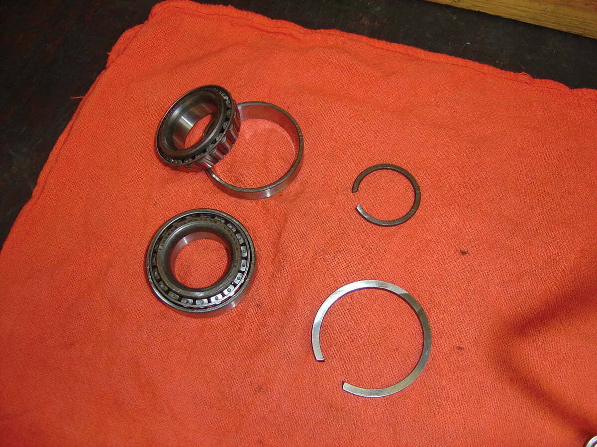
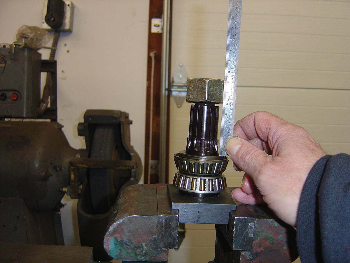
Leftside or powerside Timken bearing assembly. Two bearings, two races, one large spacer for the races and the small spacer for endplay. These come as a set—be sure to keep them all together.
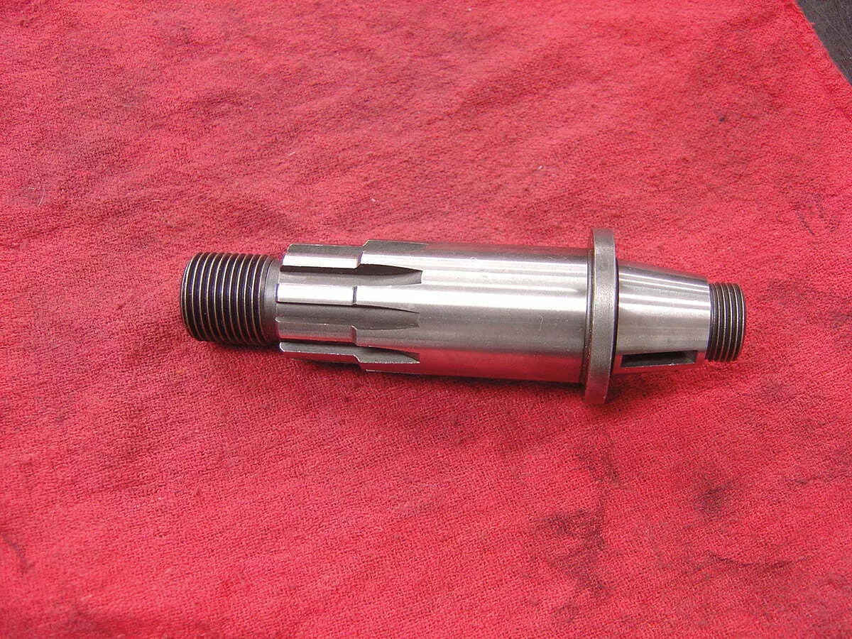
Locate a powershaft. A used one will work fine. Harley recommends PN 24001-72 or 23909-80. You’ll also need a nut for the primary drive side.
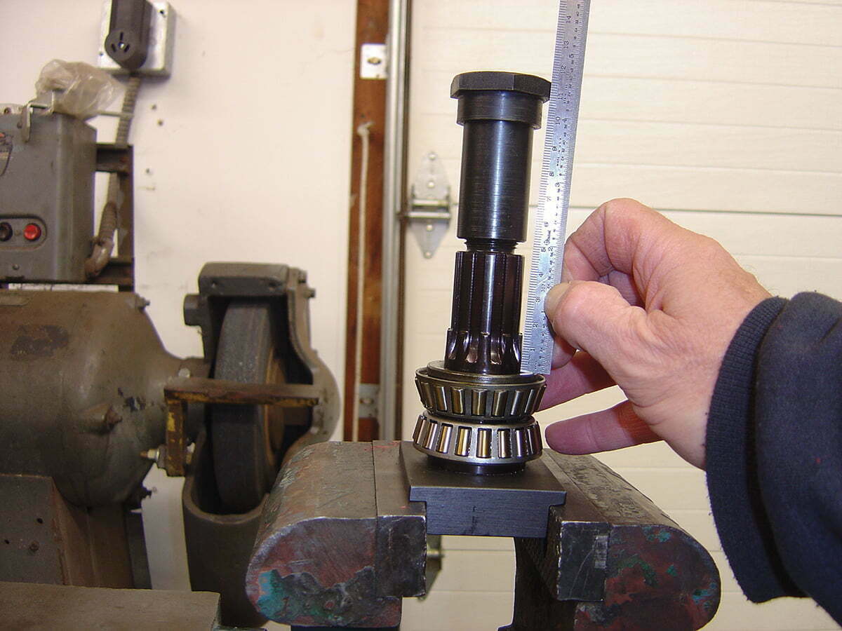
We used this shaft. Notice it doesn’t have a taper, it was left over from a drag bike project. It is meant to be pressed into a racing flywheel and welded.
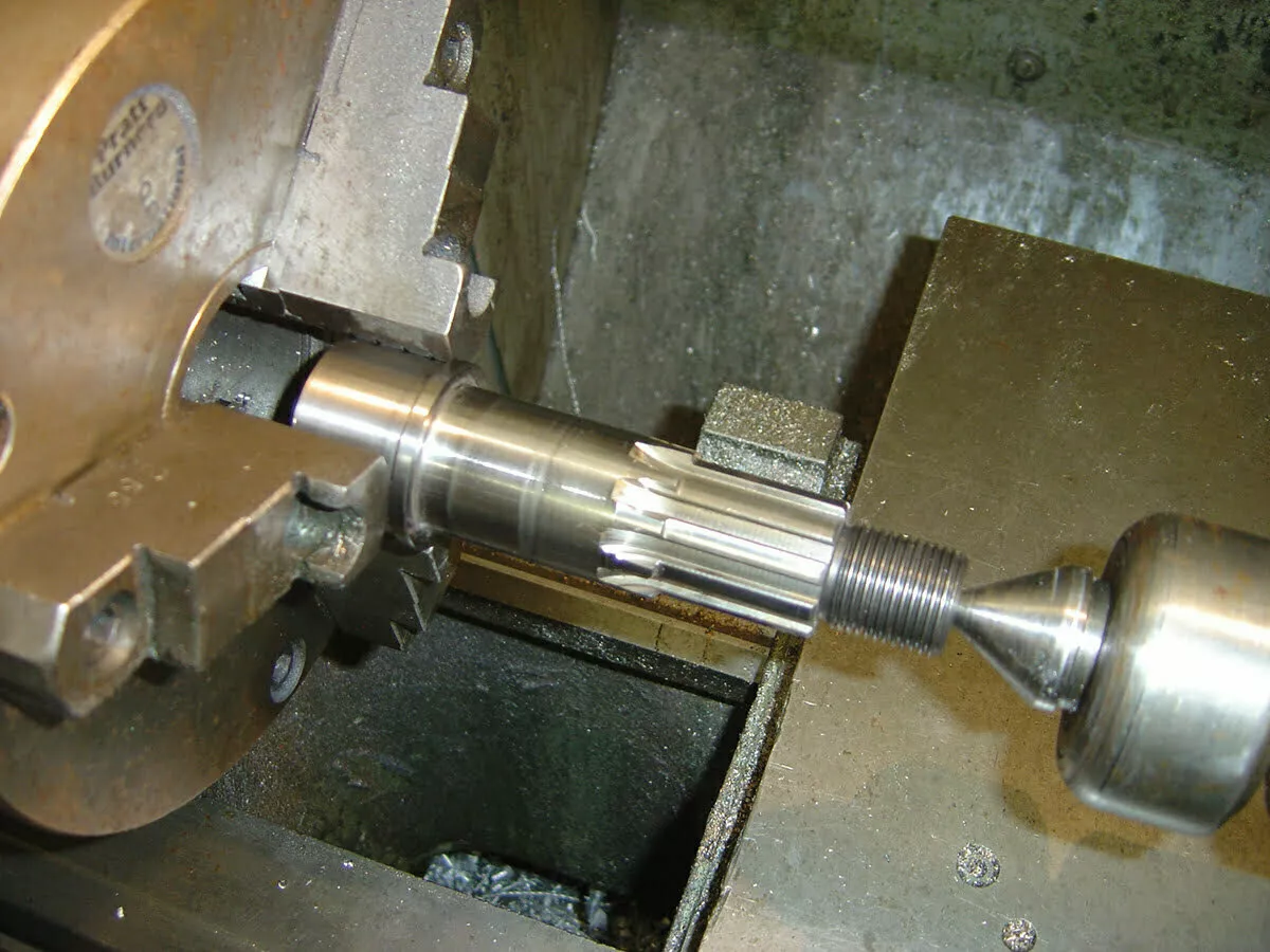
With a tapered shaft gently clamp on the splines. Don’t clamp on the shoulder, if it becomes damaged the bearing won’t seat correctly.
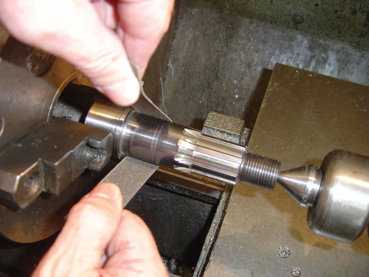
Once in the lathe, turn at a slow speed and lightly sand the shaft.
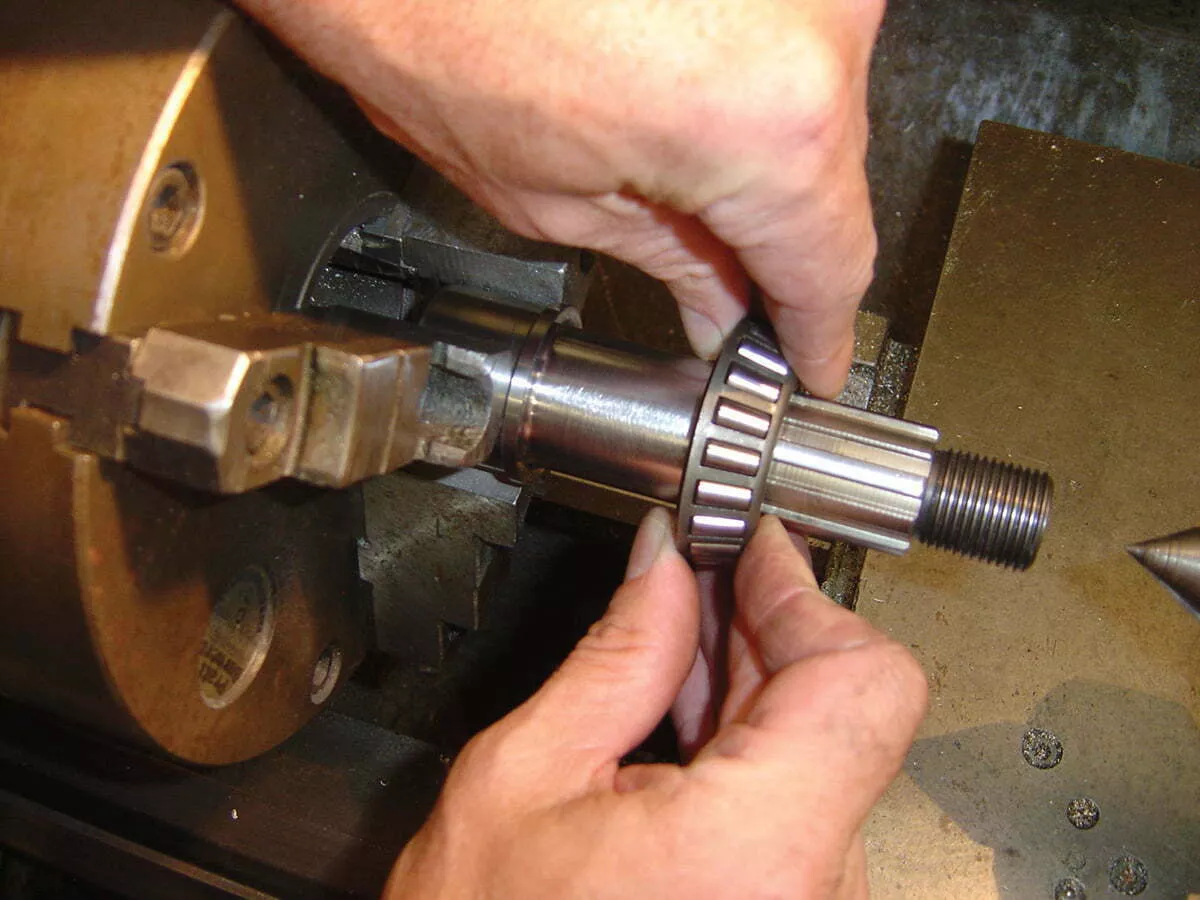
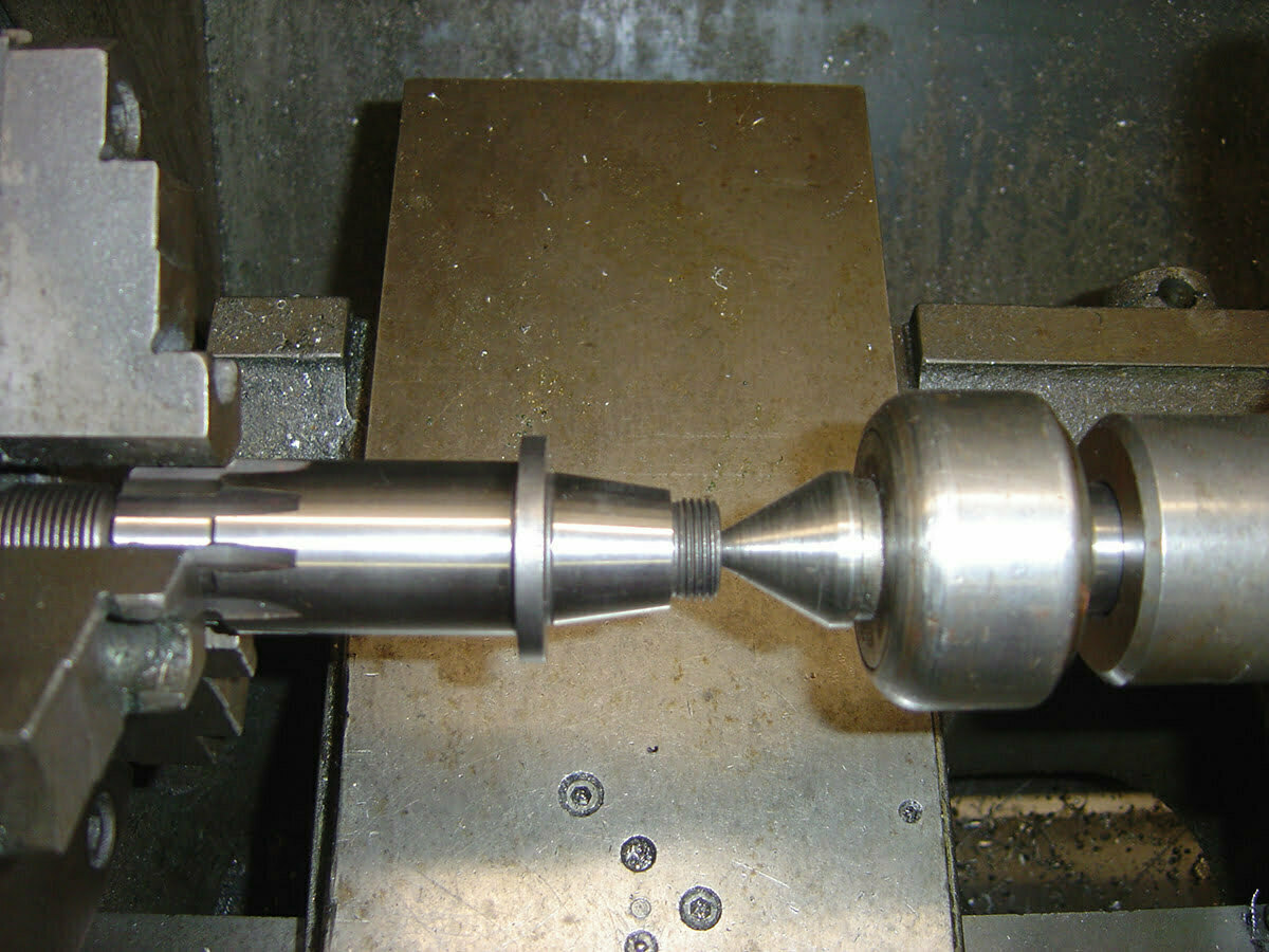
Using a bearing, check your progress often. We’re looking for a slip fit.
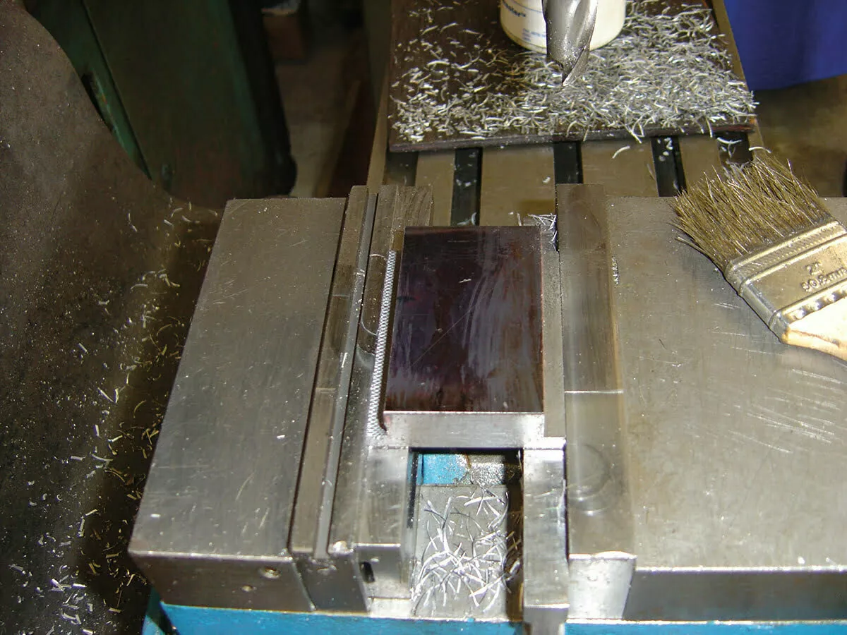
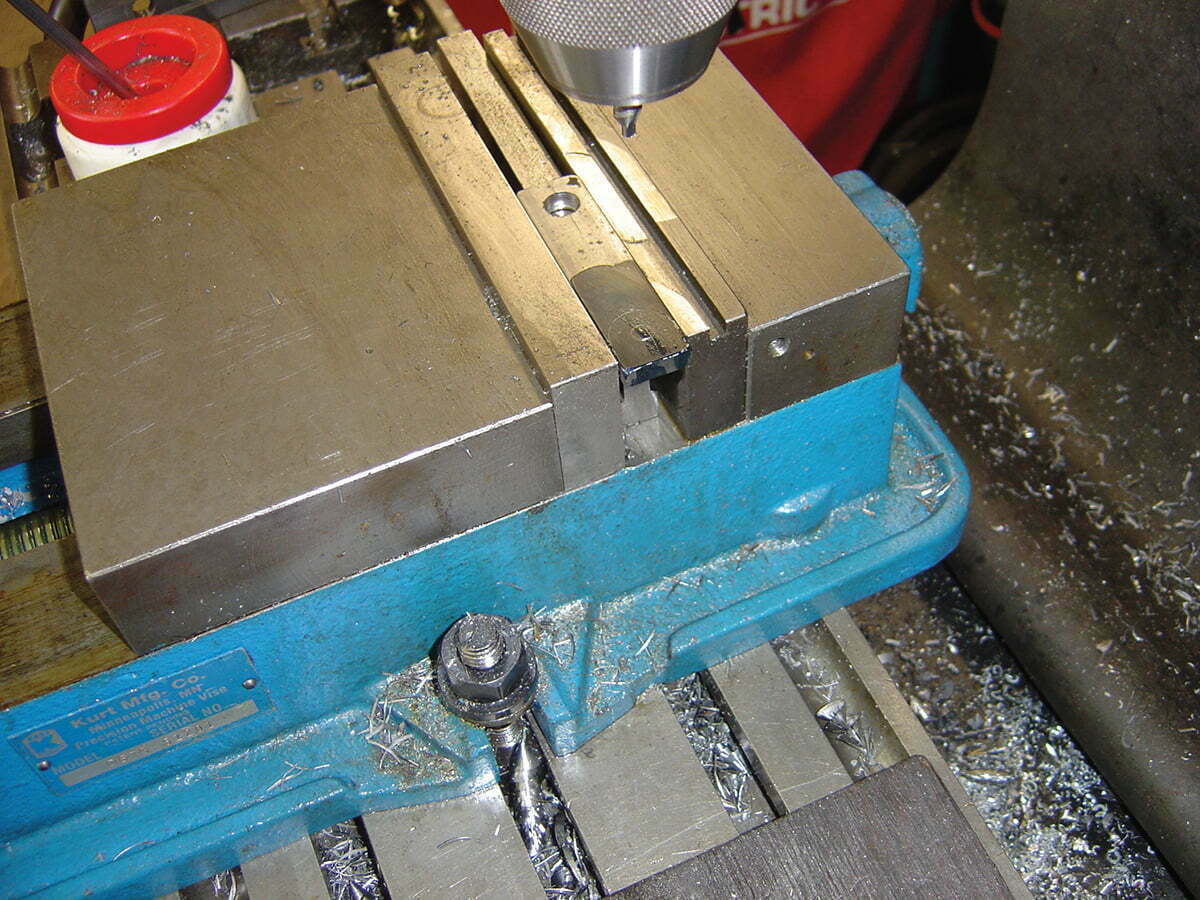
Once the shaft is to size, we need a way to hold the shaft. We decided to make ours portable, a T-nut will allow us to clamp it in a vise. We put a piece of 2x3x3/4 steel in the vise and milled off both sides a little over half way down.
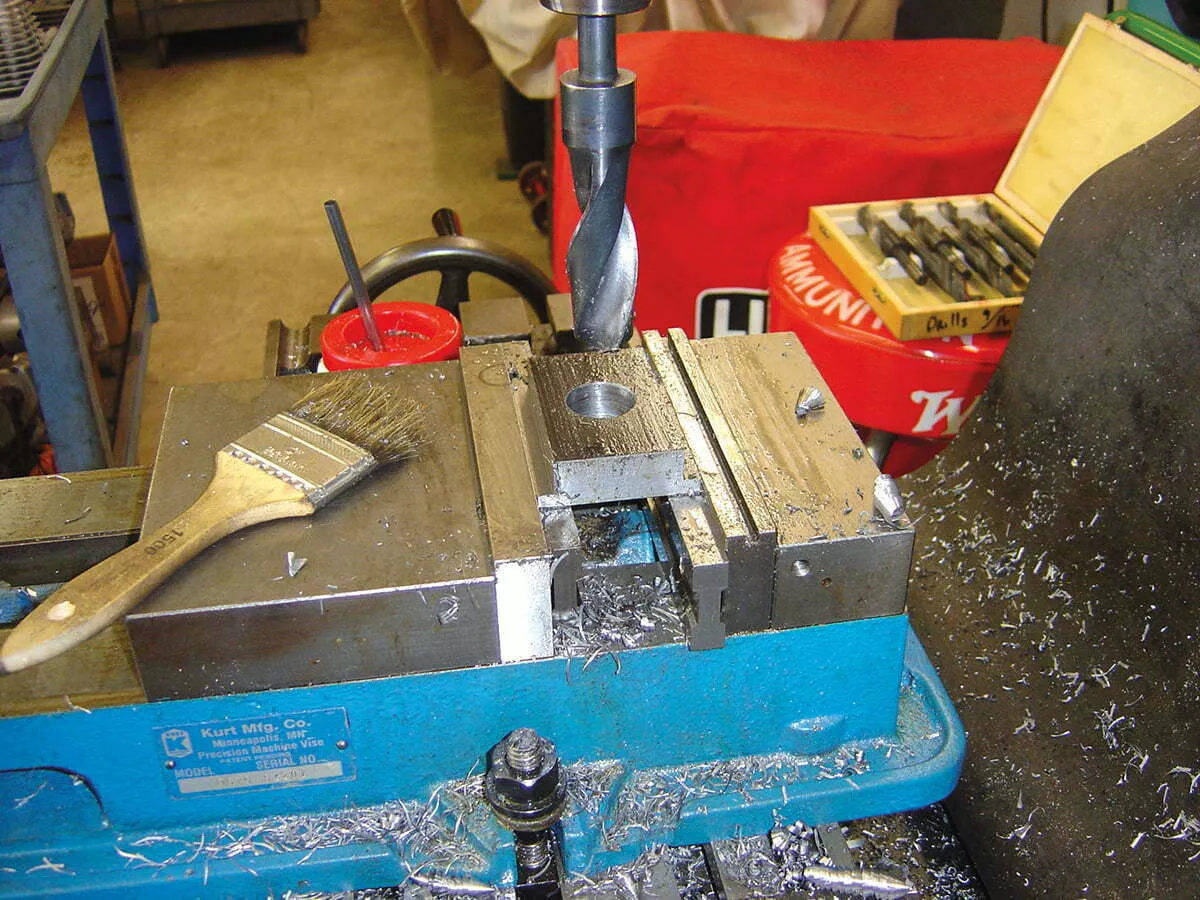
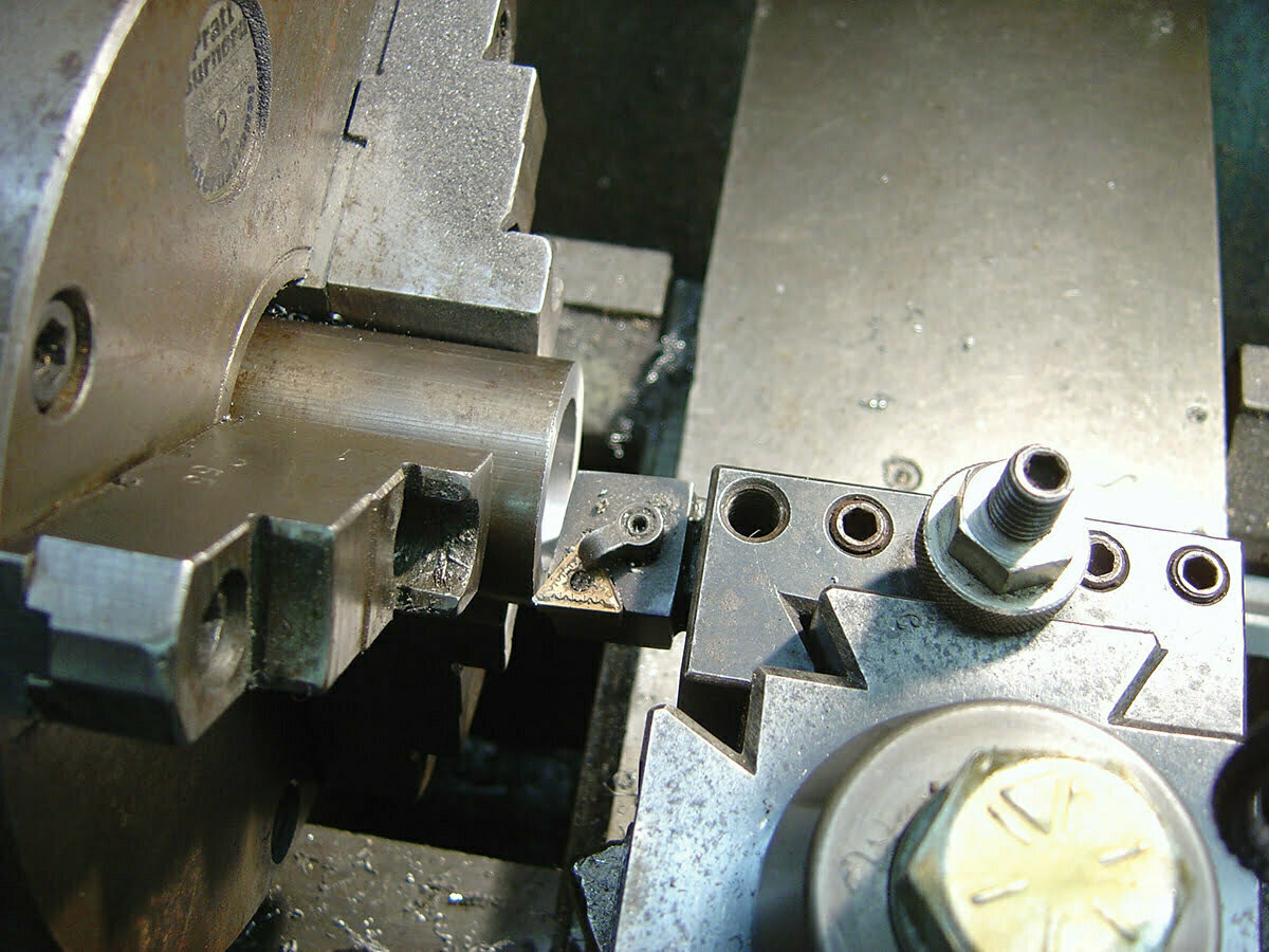
Our shaft was 1.500 inches OD so we drilled it with our largest drill bit (1-inch).
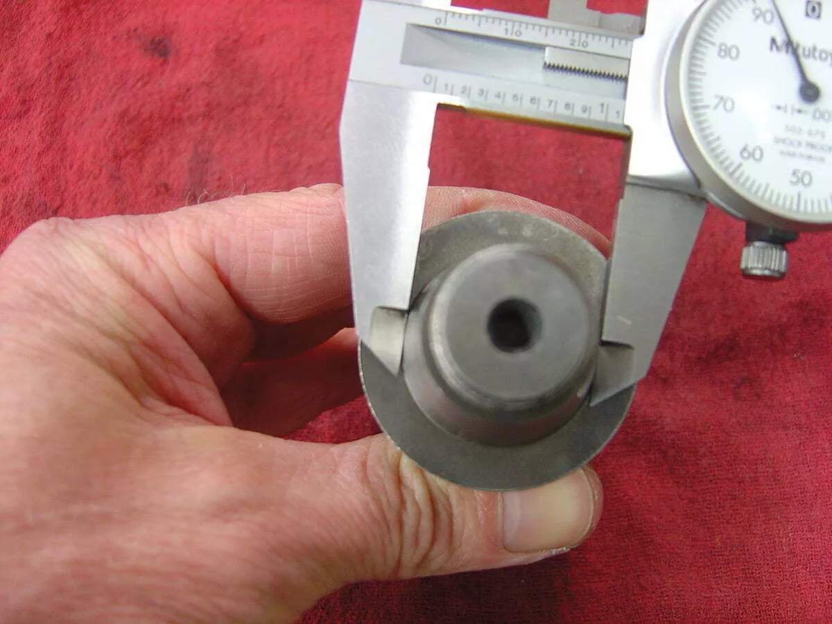
For a taped powershaft measure and drill the hole to the large diameter.
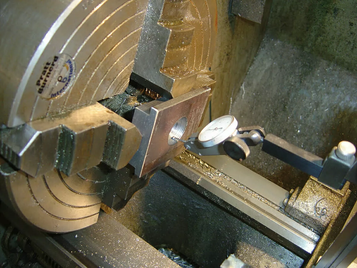
Since the hole was too small we went back to the lathe. We chucked our base plate up in the four jaw and indicated in the hole.

We then bored it to from 1-inch to 1.5 inches. With a taper shaft, bore it to the large taper diameter. There is no need to bore a taper in the mounting block.
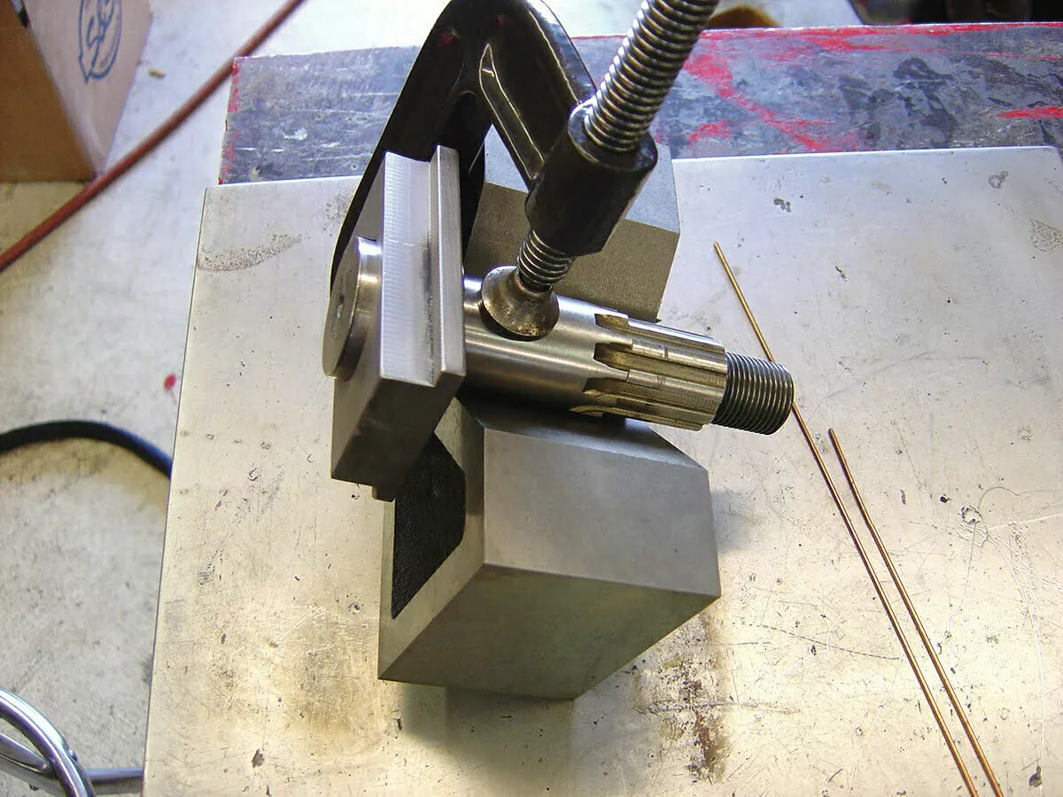
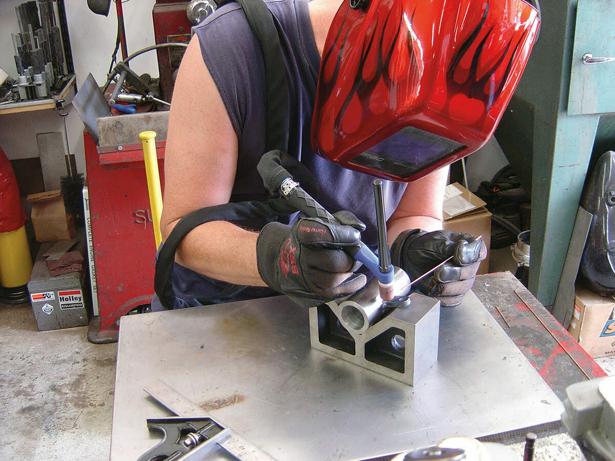
Using a V-block, we clamped everything together making sure it was all square.
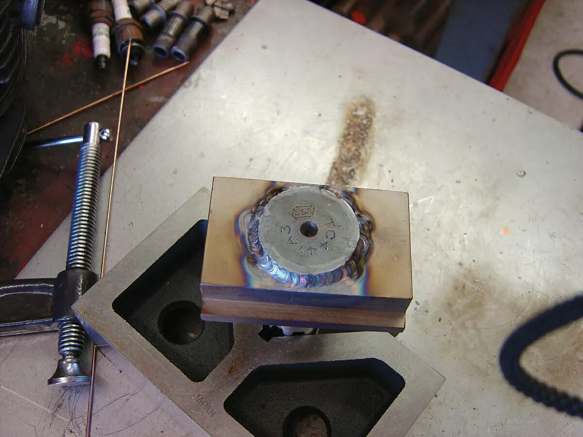
The TIG welder was out so we used it to weld the shaft to the base. MIG or stick will work fine just make sure you get plenty of penetration with the base metal.
A spacer is needed to fit
between the nut and outer
bearing. It will also hold
the dial indicator. Length
will vary based on the nut
used. Mock-up the tool
with bearings and inner
spacer. Take a measurement
between bearing and nut.
Insure there is full thread
engagement with nut on
the shaft and space below the nut to allow room for tightening.
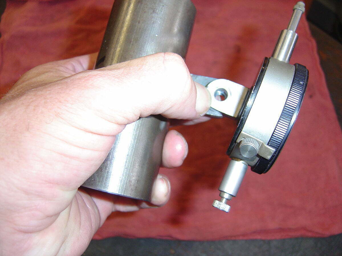
A standard nut will work, but we used a sprocket nut off a shovelhead. It’s longer which gave a us more room for the dial indicator. Same as with the standard nut, screw it down until there’s a little gap at the bottom and take a measurement.
We chucked up a piece of metal tubing in the lathe, faced it square and machined it to length. The tubing OD should be the same OD as the bearing inner race or the bearing could be damaged.
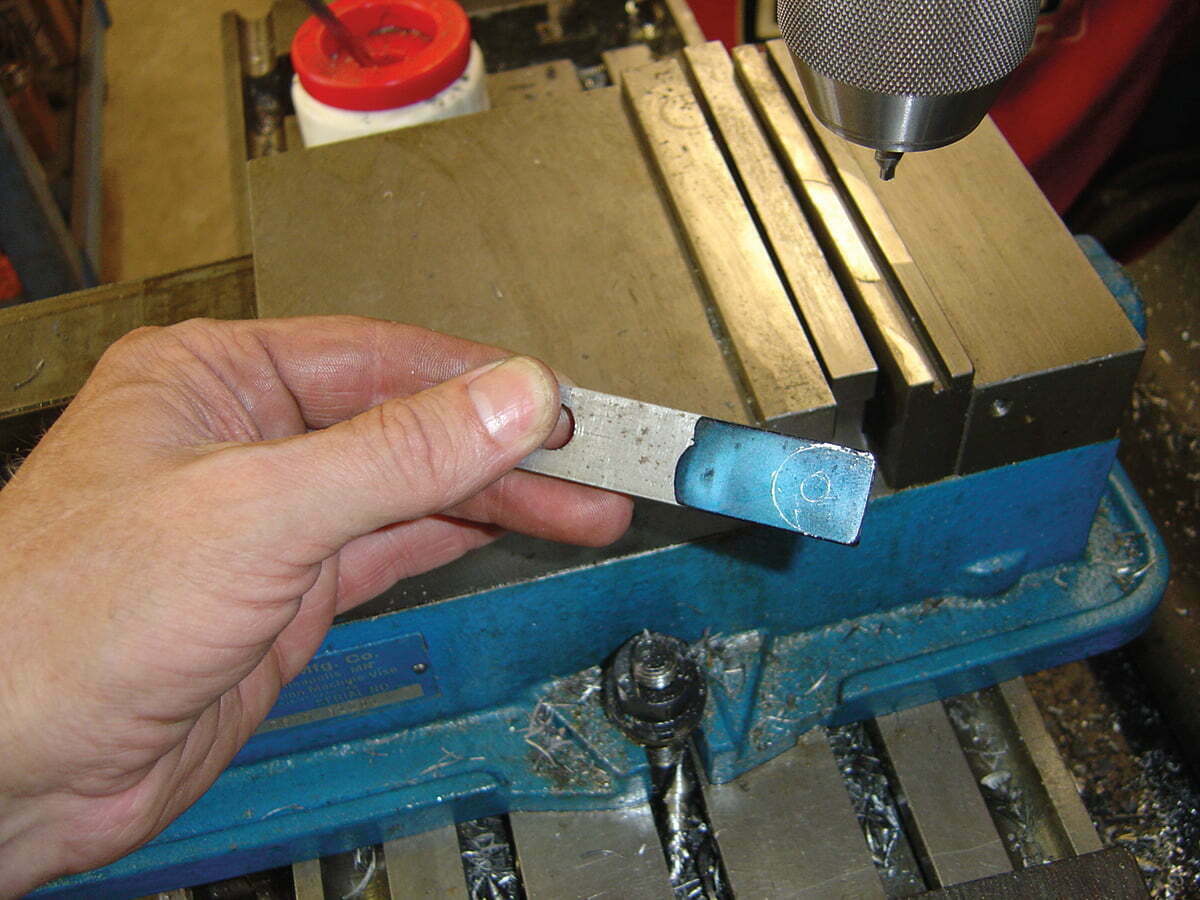
A tab is needed to hold the dial indicator. We used a piece of scrape. Using the indicator tab as a template we blued up the piece and scribed the outline.
Next we drilled a #7 hole in the tab and tap the hole 1/4×20.
We used the V-block again to hold the tubing and tab square for welding.
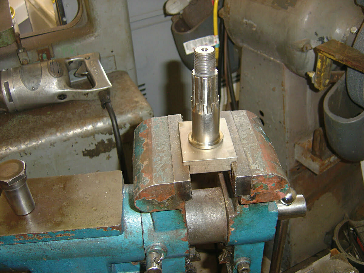
Lock the base securely in a vise. If you wanted, you could change the base plate design and bolt it to a work bench. Be- cause of the shape of the leftside engine case the tool would have to stand taller for more clearance than the vise model.
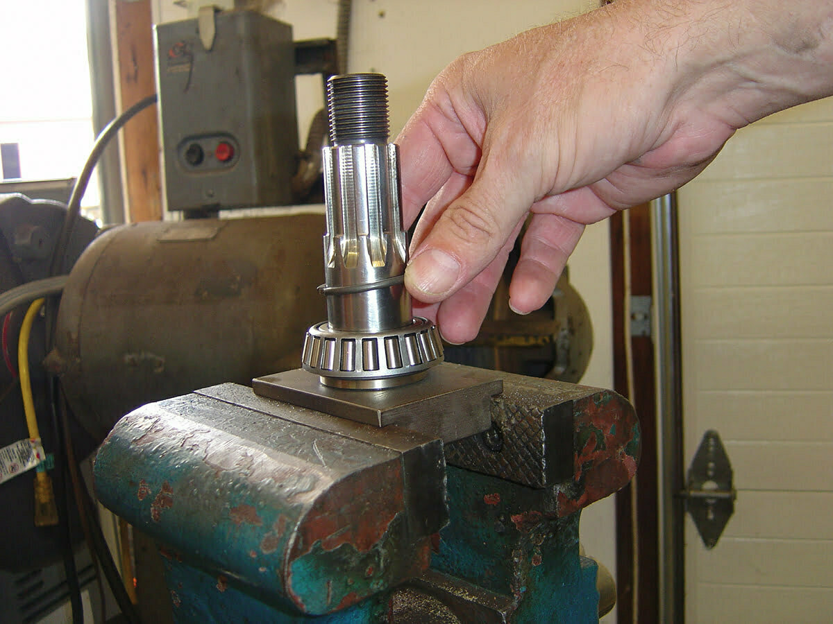
Install one of the bearings and the spacer ring.
Here you can see we have installed the bearing races in the left side case. Place the case on the bearing tool and install the other bearing.
Mount the dial indicator to the spacer tube with a 1/4×20 bolt.
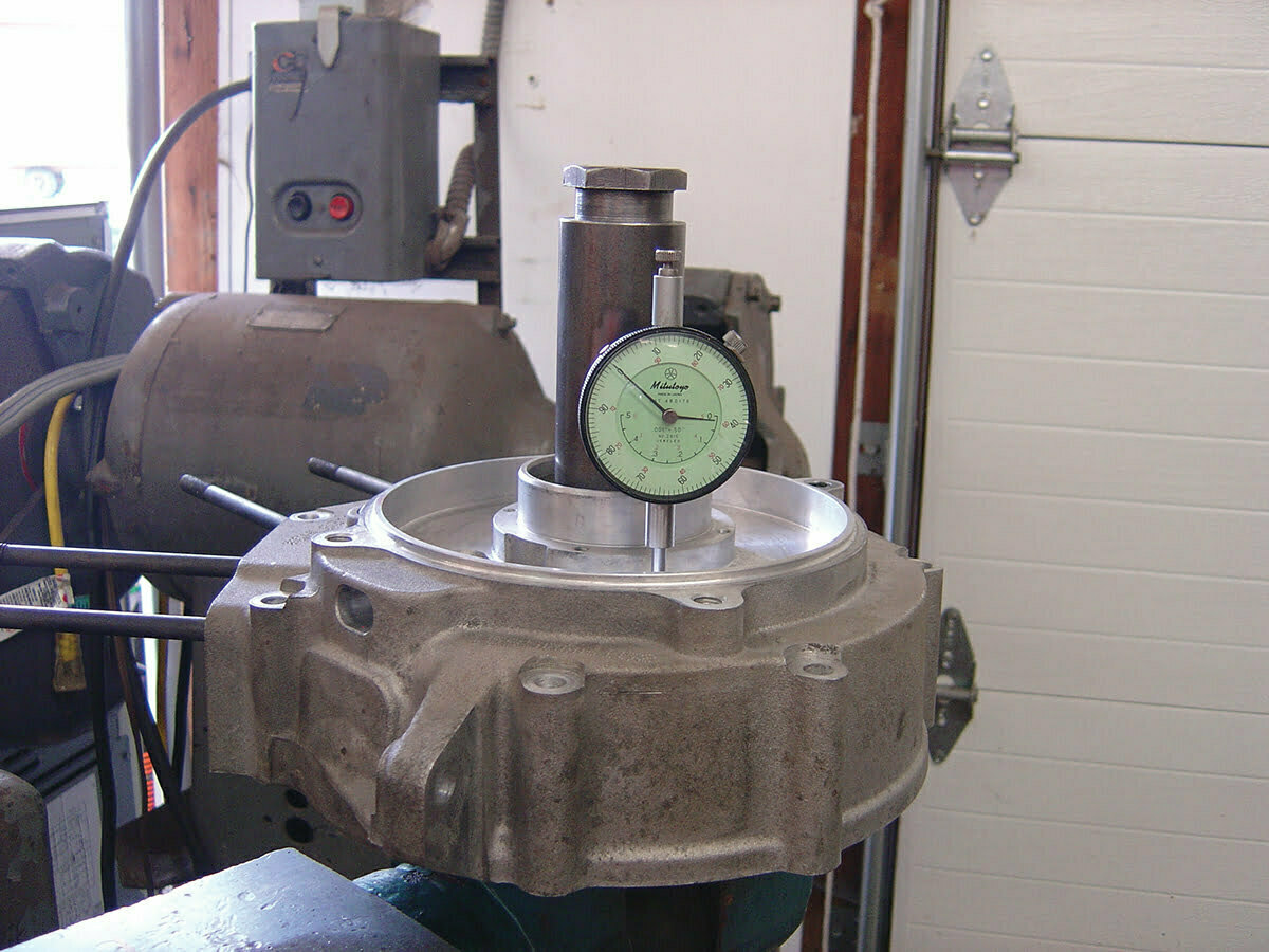
Install the tool spacer/indicator and nut. Tighten the nut down securely.
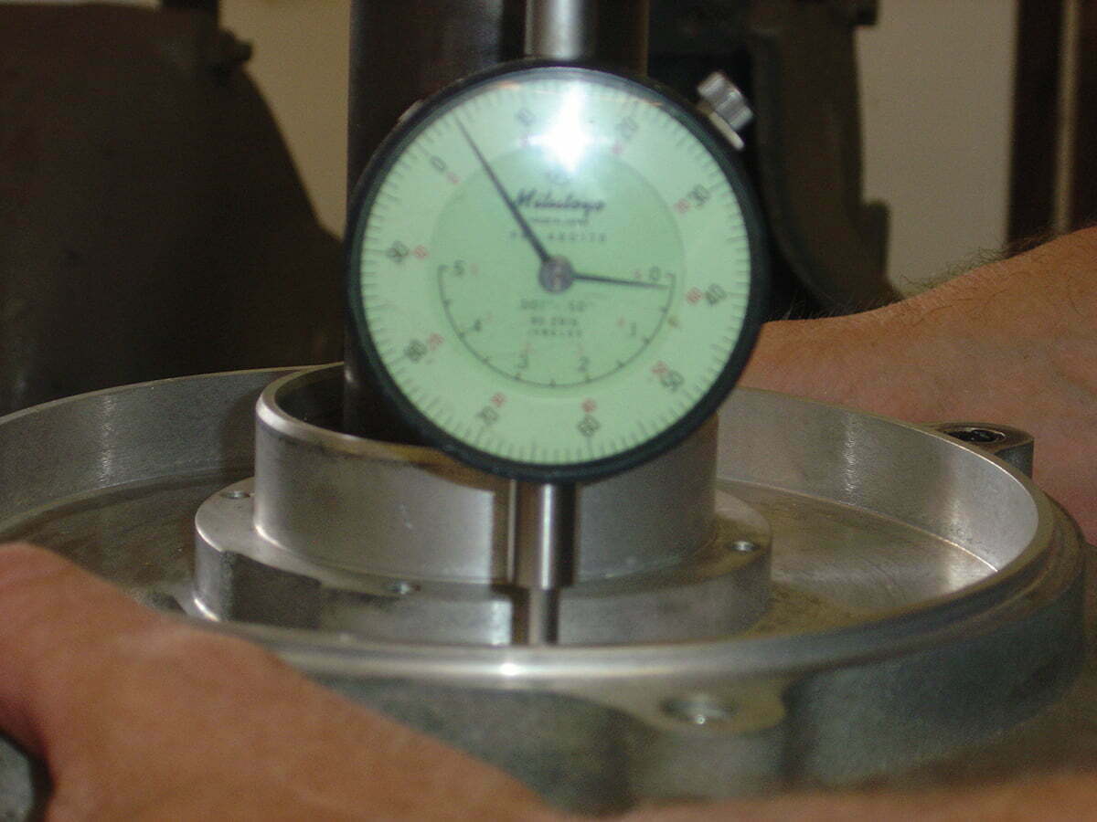
Zero the in- dicator and lift up the engine case, noting the clearance. Double
check the
measurement
by rotating the
case, checking
in three places.
If it’s out of spec it’s easy to pull apart and select a new spacer.
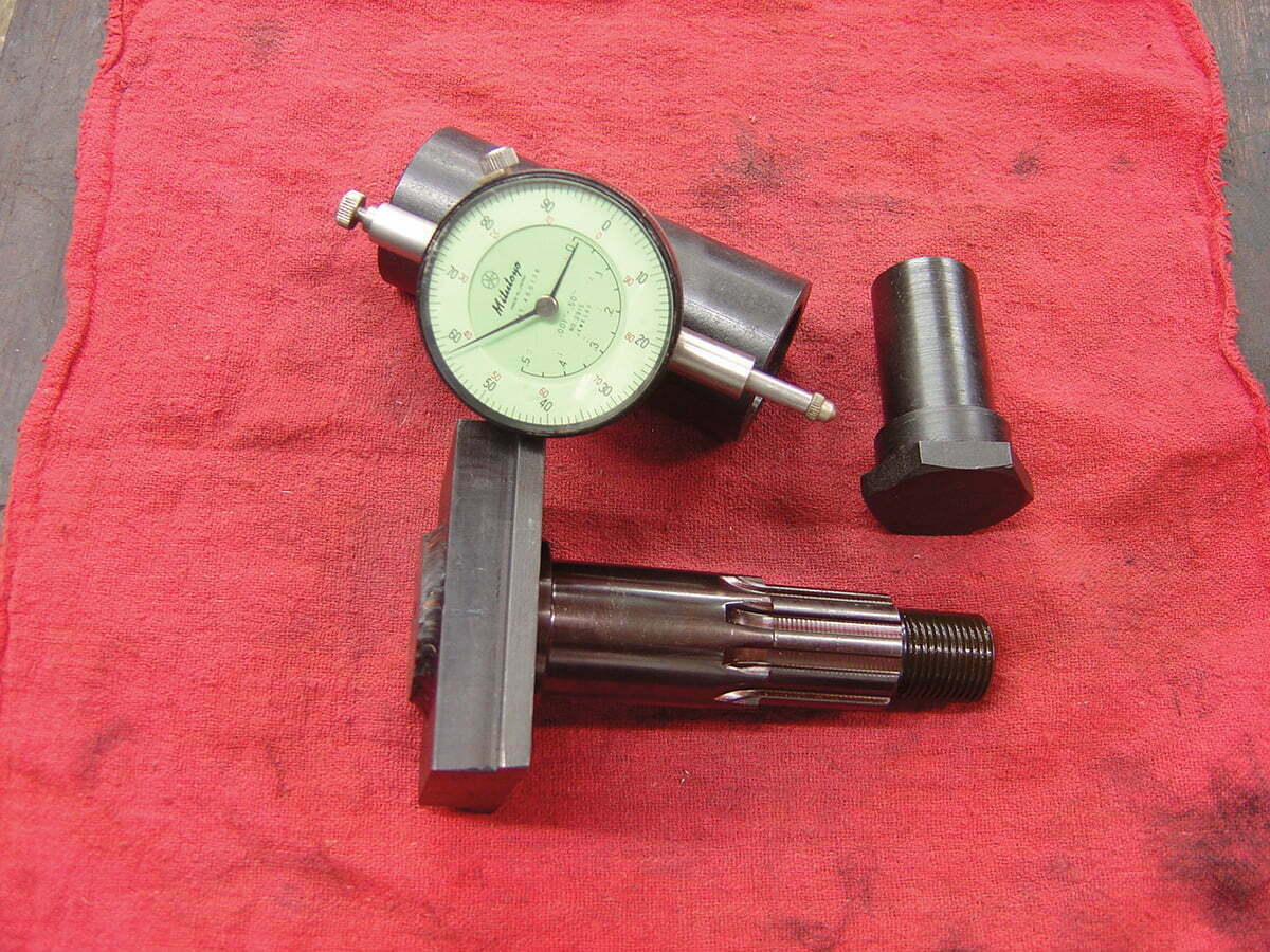
Here’s the whole set-up. It’s nice to have a dial indicator dedicated to this tool so we don’t have to chase one down. We had other stuff going out for black oxide and sent this along. It works as good as it looks and should give a lifetime of service.
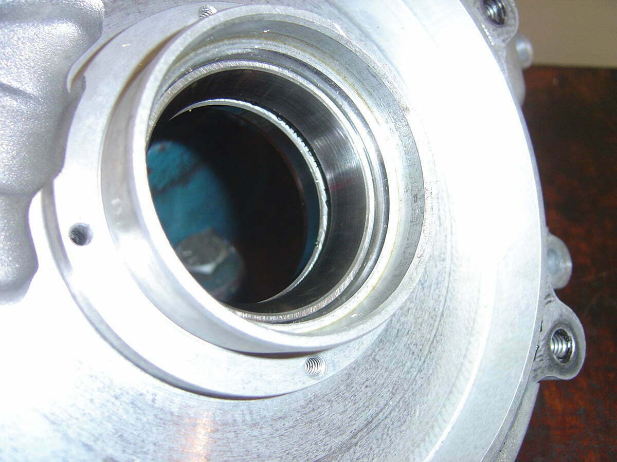
Installing flywheels into engine cases can be a painful experience on ’03 and earlier twin cams, all EVOs, Shovels and Pans back to ’55. 1955 was the year harley changed the left side bearing to a timken tapered bearing. This
is the same bearing that is used as front wheel bearings on most automobiles. This set-up is just about bullet proof, if timken bearings can support a car for 100-thousand miles, engine duty is a piece of cake.
to install these flywheels correctly requires setting end-play. This is how much side-to-side clearance the flywheels have inside the engine cases.
There’s a really old specialty tool from h-D for checking end-play. it attaches to the left side shaft, the flywheels are shoved to the right, and the locating pin is pushed against the engine case. The flywheels are then shoved back to the left and a feeler gauge is used to measure the distance between the pin and engine cases. Not very high tech but it works.
Problem is the cases and flywheels have to be assembled. if the clearance is incorrect you have to disassemble the cases, measure the spacer, select a new one, and do it all over again until it’s done right. During the eVo days, the factory manual suggested mak- ing a tool out of an old left side powershaft to make the process easier.
There are a few companies that sell them. but, our philosophy is: if you buy it, you can’t make it, and where is the fun in that? Follow along as we build one. if you install flywheels often or only occasionally you’ll find this tool to be a big time saver.


