
Ready for a Boost! | Trask Performance Turbo, Part 2
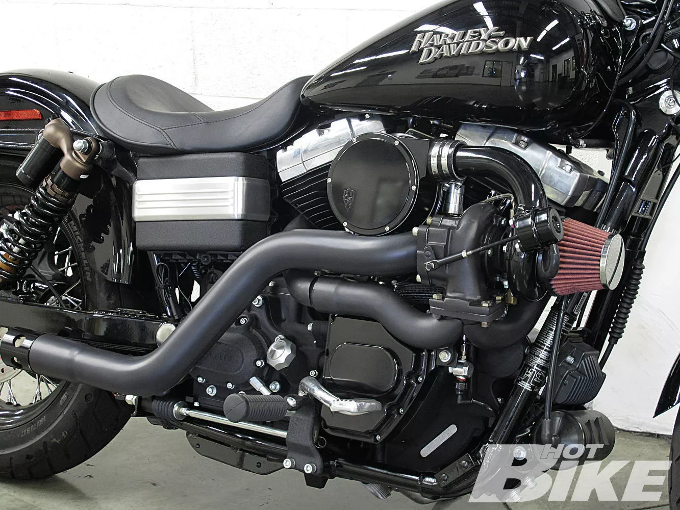
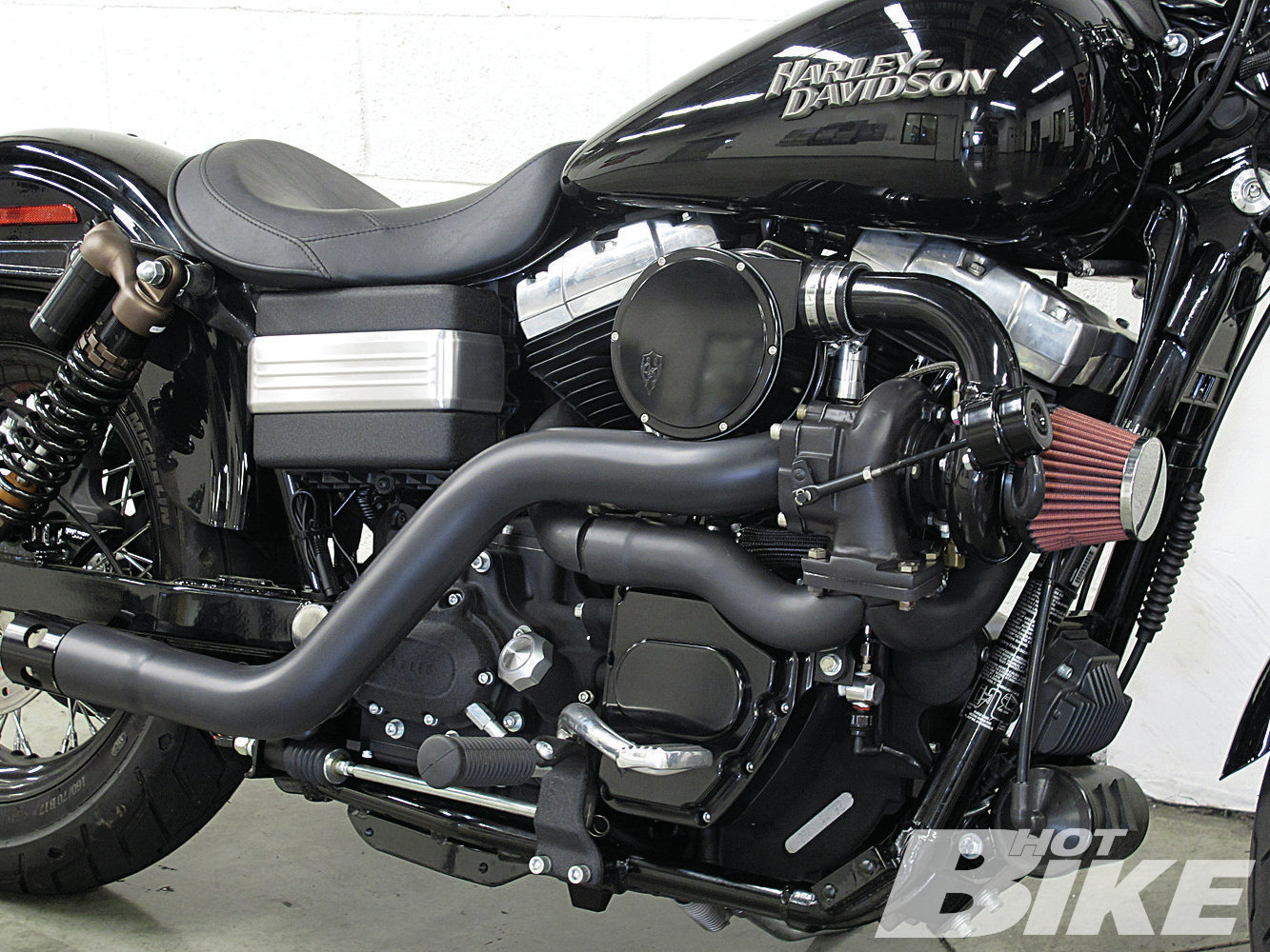
01. Nick Trask and his Trask Performance crew created this blacked-out Turbo kit for Ron’s bike. The Trask Turbo kit ($4,995) is designed for carbureted or EFI ’00-later Softails and ’99-later Dynas. Some of the main components include: the exhaust manifold and exhaust pipe with heat shields, turbo housing, plenum, boost gauge, billet breathers, air filter, Zipper’s two-bar sensor, billet cam support plate, and a Barnett high-performance clutch spring.
01. Nick Trask and his Trask Performance crew created this blacked-out Turbo kit for Ron’s bike. The Trask Turbo kit ($4,995) is designed for carbureted or EFI ’00-later Softails and ’99-later Dynas. Some of the main components include: the exhaust manifold and exhaust pipe with heat shields, turbo housing, plenum, boost gauge, billet breathers, air filter, Zipper’s two-bar sensor, billet cam support plate, and a Barnett high-performance clutch spring.
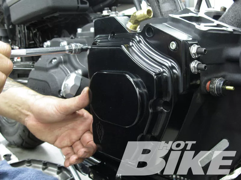
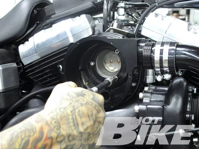
02. In the last article Matt had already replaced the stock clutch spring with the Barnett high-performance unit. So Matt started the install by swapping out the stock cam cover with the black billet Trask unit. This new cam cover has a brass oil return fitting tapped into the top of it to return oil from the turbo housing back into the cam chest.
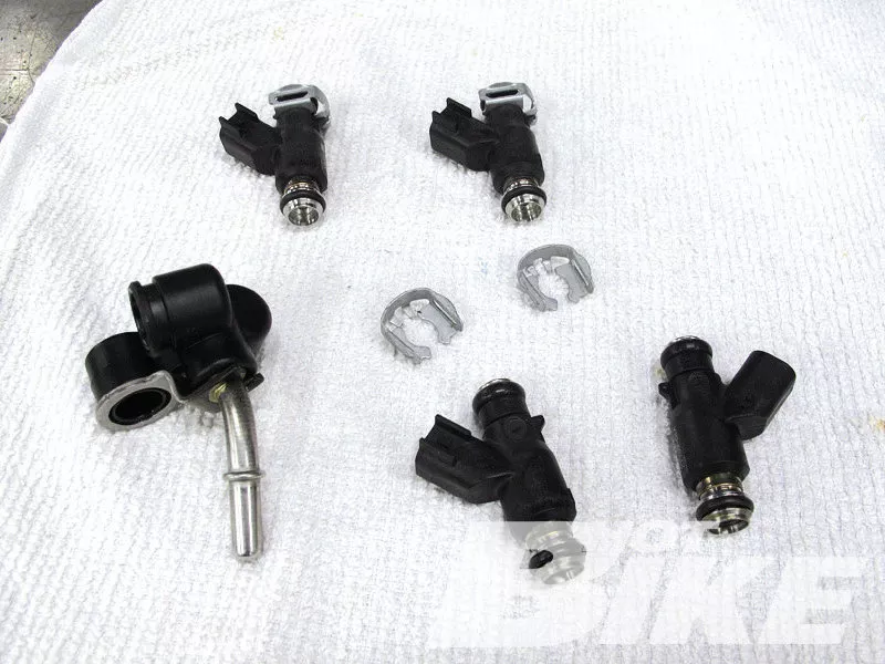
03. Next, Matt removed the fuel rail so he could replace the stock fuel injectors (bottom) with H-D’s High Flow 4.9 g/s fuel injectors (top).
04. The fuel rail with new injectors was then bolted back onto the throttle body.
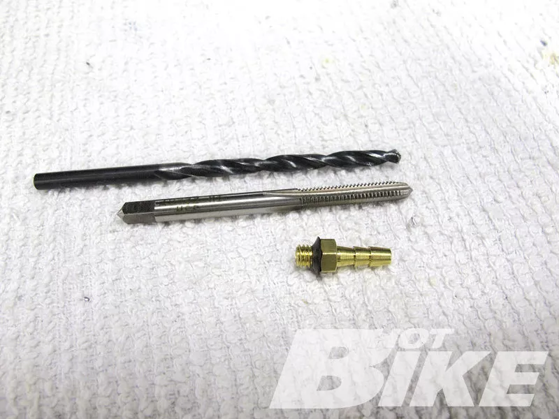
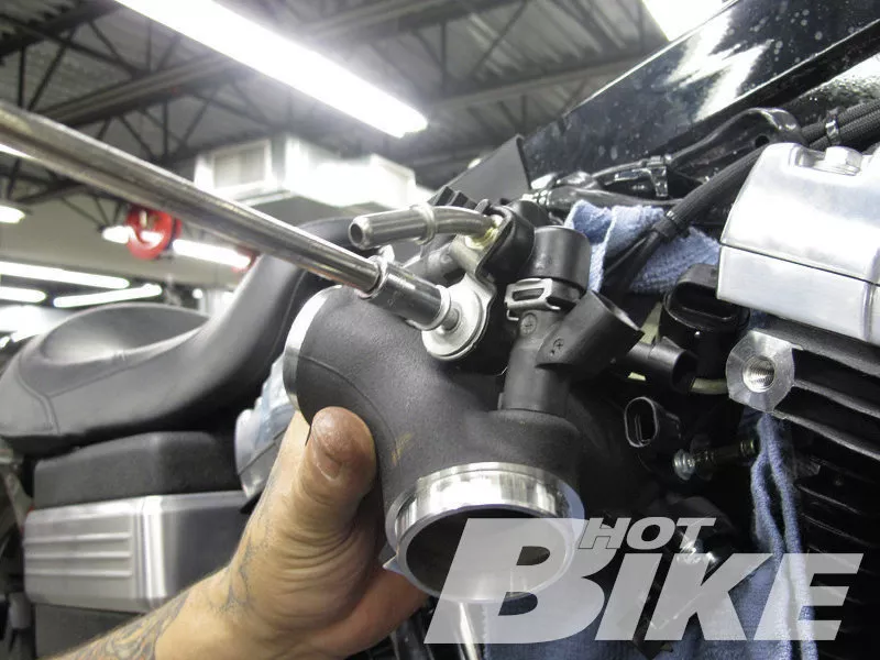
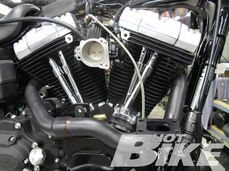
05. Before the throttle body was slipped back between the heads, Matt had to drill and tap the underside of the throttle body to thread in the brass fitting for the vacuum/blow-off-valve hose. A #21 drill bit and 10-32 tap were supplied with the kit.
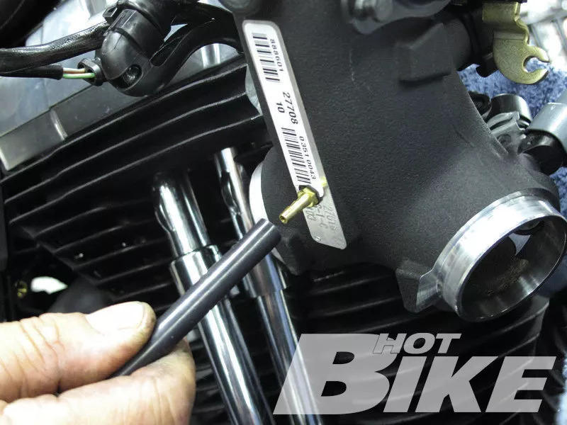
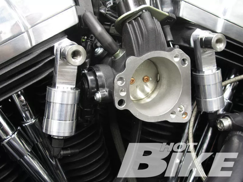
06. After thoroughly cleaning the throttle body of any metal debris, Matt installed the fitting and attached the vacuum/blow-off-valve hose.
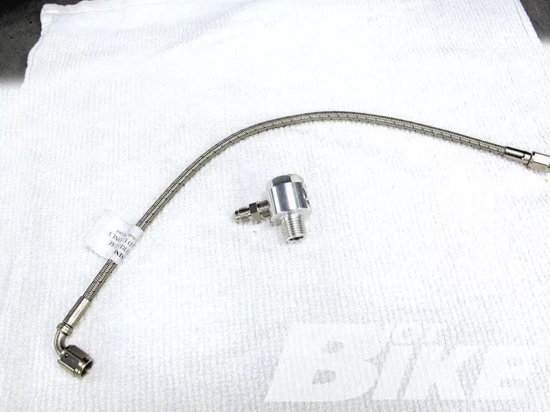
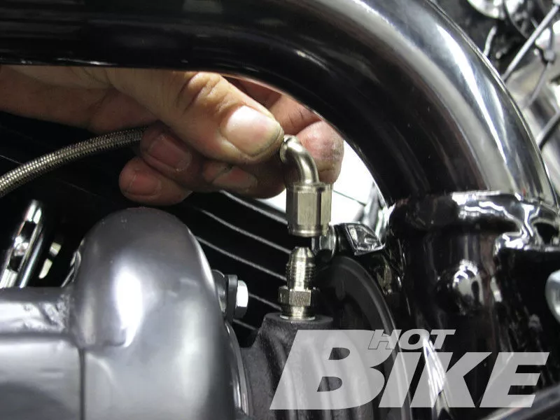
07. This aluminum adapter and steel-braided oil line come in the kit and are used to feed oil to the top of the turbo housing. The oil is used to lubricate the bearings that surround the common shaft between the turbine wheel and compressor wheel.
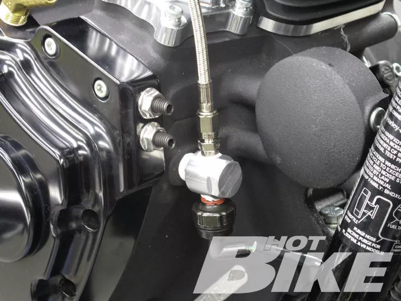
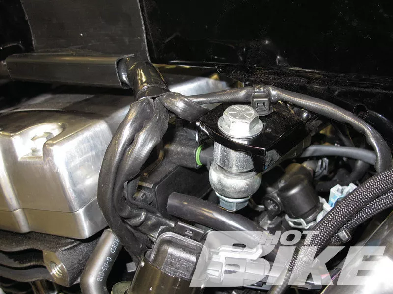
08. Matt removed the oil pressure switch and applied some thread sealer to the adapter’s threads, then installed the adapter in the stock pressure switch location. The oil feed line was then threaded into the top of the adapter and the pressure switch was threaded into the bottom of the adapter.
09. After installing the exhaust manifold mounting brackets onto the studs on the cam cover, Matt applied some RVT silicone inside the slip fit on the exhaust manifold. He then slid the two manifold pipes together and loosely bolted the manifold assembly to the heads using the stock exhaust flanges.
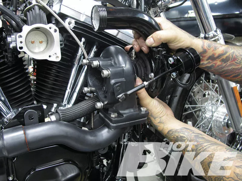
10. The oil drain line was then connected to the fitting on top of the cam cover and to the bottom of the turbo housing. The turbo was then loosely bolted to the exhaust manifold.
11. Matt then loosely bolted up the front of the exhaust pipe to the back of the turbo. The rear of the exhaust pipe was loosely bolted to the supplied exhaust bracket that mounts to the back of the transmission.
12. The oil feed line was connected to the top of the turbo housing.
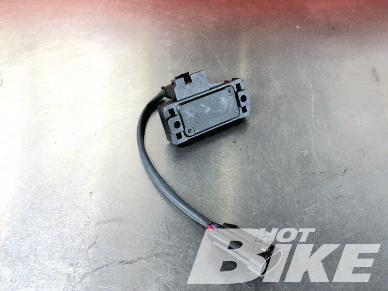
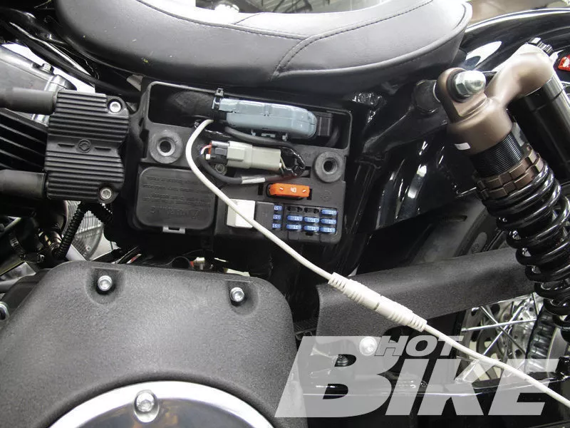
13. For EFI setups Trask recommends the Zipper’s Thunder Max with Auto Tune. Trask prefers this system because of its extensive and in-depth tuning capabilities. Included is a CD with proper mapping to be loaded into Thunder Max. To go along with the Thunder Max is a two-bar map sensor (pictured). This two-bar map sensor reads boost pressure and feeds a signal to the Thunder Max so the system can add fuel or retard timing, and make adjustments as needed.
14. Matt followed Zipper’s instructions for installing the two-bar map sensor then tucked the sensor between the throttle body and rear cylinder so it was out of the way.
15. Matt then installed the billet Oil Mister Breathers that came with the kit.
16. The boost gauge and blow-off-valve lines were then connected to the back of the plenum, then the plenum was bolted to the throttle body.
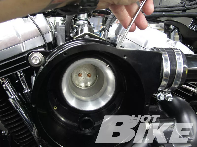
17. Matt installed the velocity stack (arrow) inside the plenum, then…
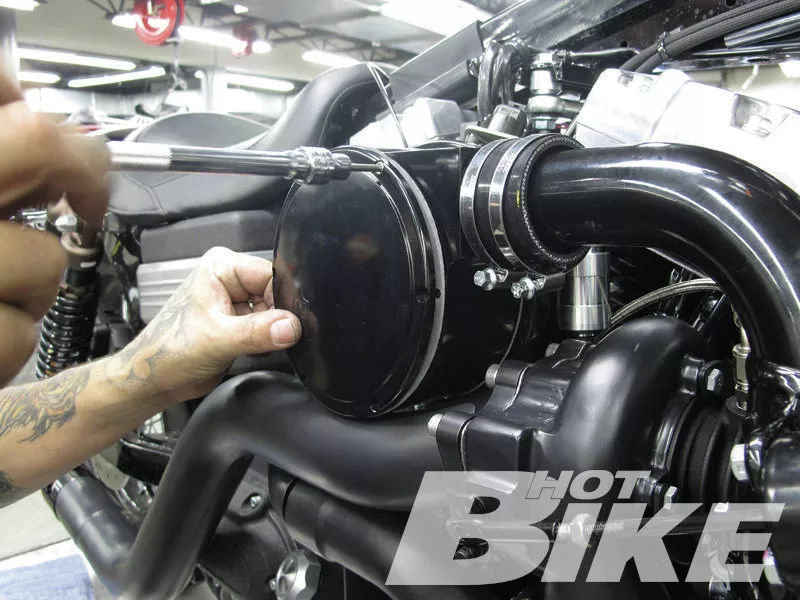
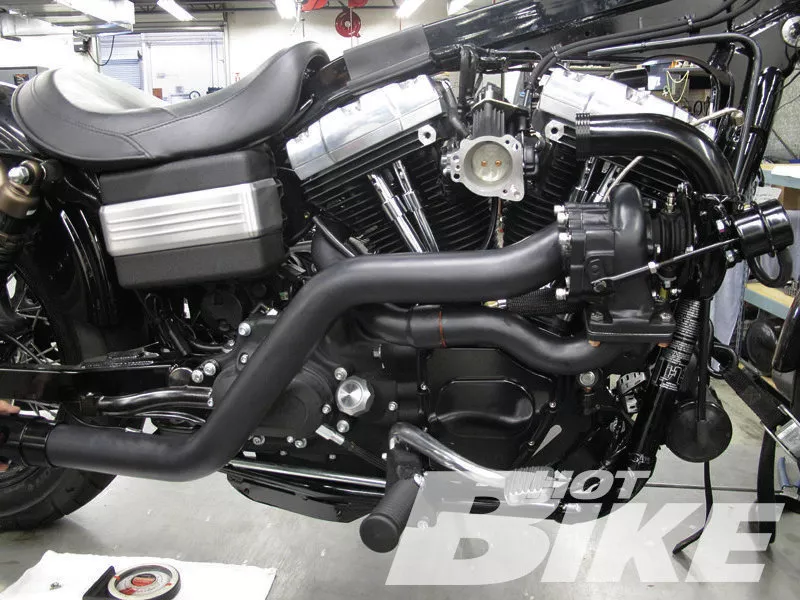
18. …he bolted on the plenum’s outer cover and tightened down the silicone connector (arrow) between the plenum and turbo tube using the supplied hose clamps.
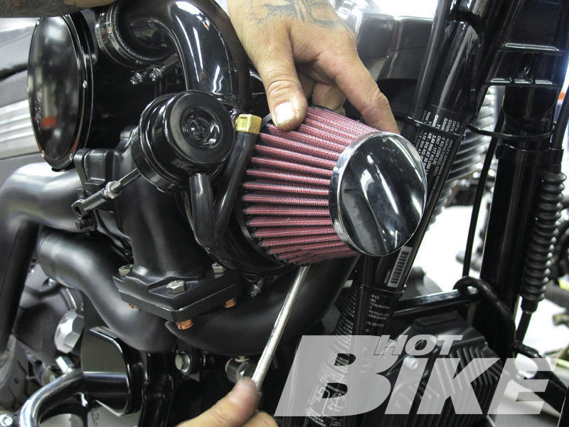
19. After installing the heat shields onto the exhaust manifold and exhaust pipe, Matt secured the high-flow air filter to the front of the turbo housing.
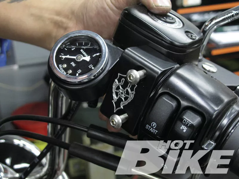
20. Up at the right-side hand control, Matt removed the stock throttle-housing clamp and replaced it with the Trask boost gauge/clamp. He then connected the plastic 1/8-inch boost gauge line to the fitting on the bottom of the boost gauge.
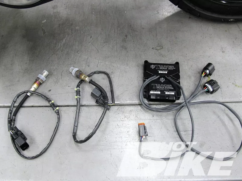
21. Nearing completion, all that was left to do was install the Zipper’s Thunder Max with Auto Tune system. The Zipper’s Thunder Max with Auto Tune is a wide-band, closed-loop system that continually monitors the exhaust and automatically adjusts the air-fuel ratios as you ride. The system is very advanced providing extensive tuning capabilities and allows you to continually modify and improve the performance of your bike while maintaining optimal air/fuel ratio.
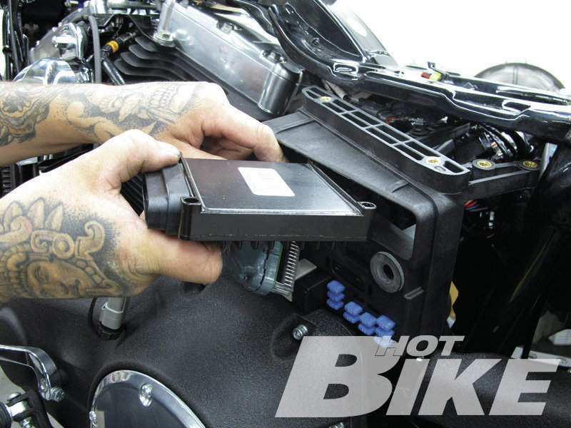
22. Matt followed the instructions for removing the stock ECM and installing the Thunder Max ECM.
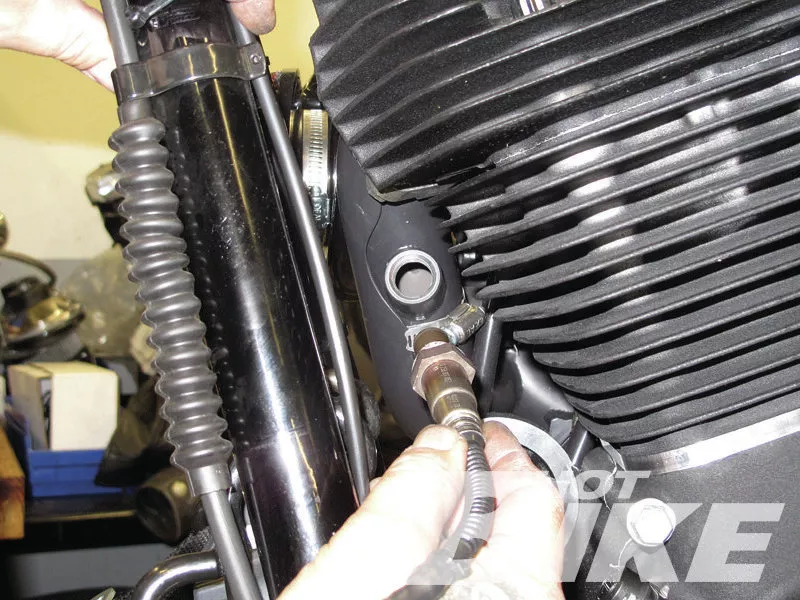
23. Once the Thunder Max ECM was installed, the supplied wide-band 02 sensors were installed into the exhaust manifold.
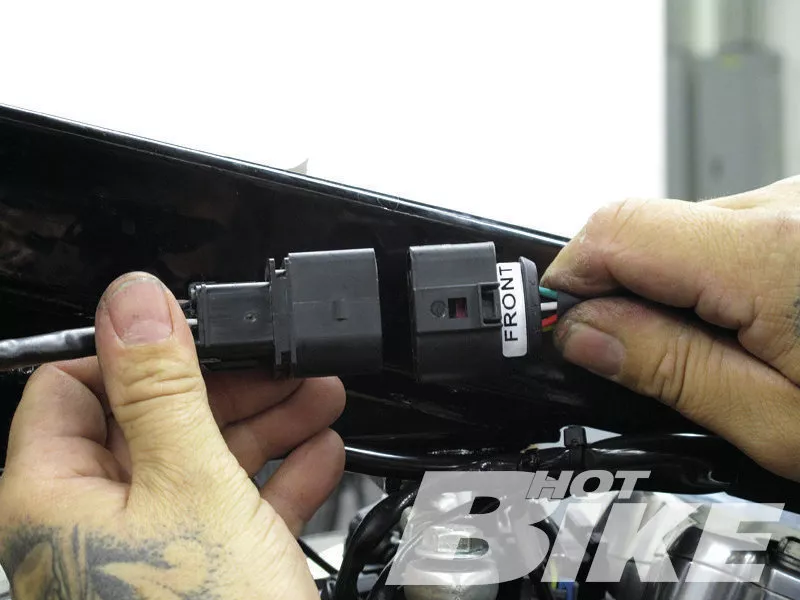
24. Lastly the new 02 sensors were connected to ECM sensor leads.
25. Matt wired this Thunder Max Pigtail Communication Harness into the stock 36-pin ECM wiring harness connector. This communication harness serves as a remote port for the Thunder Max communication cable on bikes with limited access to the standard port. With this cable installed Matt could easily connect to his laptop and load in the base map Trask Performance supplied with the kit.
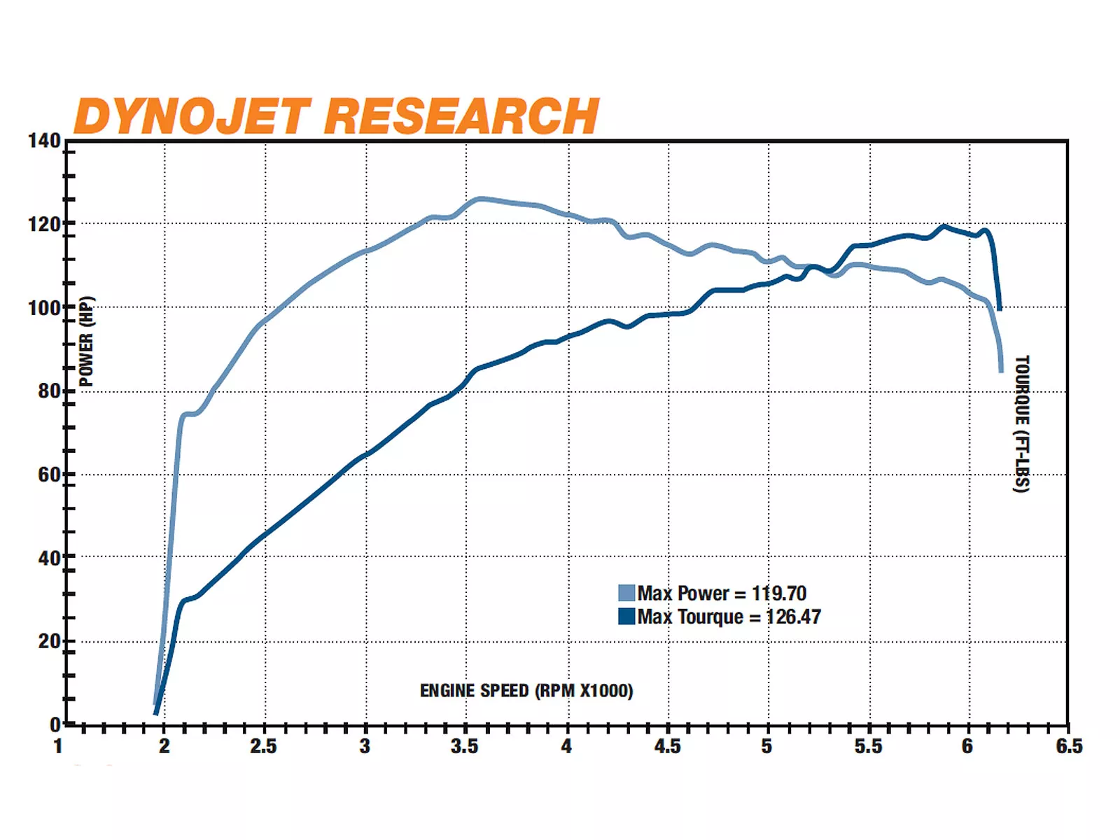
26. After the base map was installed and the bike was properly dialed in, the installation was complete. The bike was then taken over to the dyno for some final results. In its stock form the bike put out 65hp and 82lb-ft. of torque. After installing the Trask Turbo the bike put out 119.70hp and 126.47lb-ft of torque, an increase of 54hp and 44lb-ft of torque. We were pretty happy with the results, the bike makes smooth, strong power with the torque reaching its peak at about 3.600rpm. What’s nice is that the torque maintains over 100lb-ft from 2,600 to 6,000 rpm, while the horsepower steadily climbs.
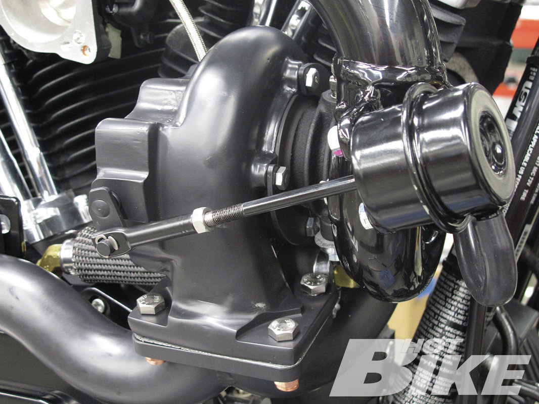
27. While Trask Performance sets its Turbo kits up with 8-pounds of boost, Nick informed us that the kit is capable of producing up to 20-pounds of boost which would make about 200hp and would require running high octane fuel. Increasing or decreasing boost can be done by loosening this locknut (blue arrow) and adjusting the rod (yellow arrow) to put more or less pressure on the spring inside the canister (red arrow). More pressure on the spring equals more boost. Another option to adjusting the boost is by purchasing a boost controller which would allow you to simply turn a dial to increase or decrease boost. Setting the kit up to produce 20-pounds of boost requires extra precautions to be made on the engine’s internal components to help withstand the significant increase in power. And while Anaheim-Fullerton H-D did make some internal upgrades to Ron’s engine, they chose to keep the boost on the mild side at about 8.5-9 pounds for the time being.
28. After putting some miles on the bike Anaheim-Fullerton H-D’s service manager, Colby Craddock reported back to us and said “It’s a different power band than most of the built motors we’ve done. We’ve built up 103ci engines with ported heads, high compression, and cams that make 120hp, so to get that same power out of a 96ci engine with just a bolt-on kit is pretty awesome. The bike is really fun to ride. Once that thing spools up and the boost kicks in, hold on!”
Moving forward with our friend Ron’s ’11 Dyna, last issue we discussed some of the main components that make up the Trask Performance Turbo kit. In that article we also showed you some of the modifications that were made to the lower end of Ron’s bike to help it withstand the additional power upgrades that would eventually be added (new cams and bumping up the displacement). Those modifications included welding the three-piece crank assembly and converting the straight roller bearing in the engine’s left-side case to a more durable tapered Timken roller bearing setup. While not required when installing one of Trask’s bolt-on turbo kits, taking care of the lower end will help Ron keep his peace of mind when he’s finished hopping up the engine and really starts flogging the bike.
Before we get into the installation of the turbo, we’ll give those of you that missed the previous article a quick recap on how this system works. A turbo system can increase power by its ability to stuff more air into the engine. The turbo system is mounted on the right side of the bike and interconnected between the engine’s intake and exhaust ports. An exhaust manifold directs the spent gasses from the engine’s exhaust ports to the turbo housing. Within the turbo housing are two impeller blades (a turbine wheel and compressor wheel) with a common shaft running between them. The velocity of the gasses spin the turbine wheel, which turns the common shaft and compressor wheel connected at the other end. As the compressor wheel spins faster and faster the air becomes compressed, charged air. The charged air exits the compressor housing at a higher velocity, then makes its way to the intake and stuffs the cylinders with more air. More air, a little more fuel, and you can create more power.
Now follow along as we show Anaheim-Fullerton Harley-Davidson Tech Matt Cortez install a Trask Turbo on Ron’s Dyna.** HB**
**Source:
Anaheim-Fullerton Harley-Davidson **
(714) 871-6563 | harleyfullerton.com
Harley-Davidson
harley-davidson.com
traskperformance.com
(623) 879-8488 | turboyourharley.com
**Zipper’s Performance **
(410) 579-2828 | zippersperformance.com


