
Street-to-Strip Hot Rod
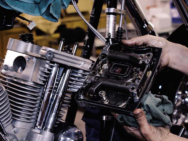
1. First, Leroy removed the dash, gas tanks, carburetor, ignition coil, manifold, and rocker boxes.
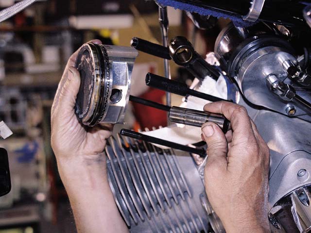
2. The heads, pushrods, cylinders, and pistons soon followed.
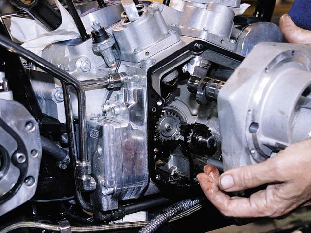
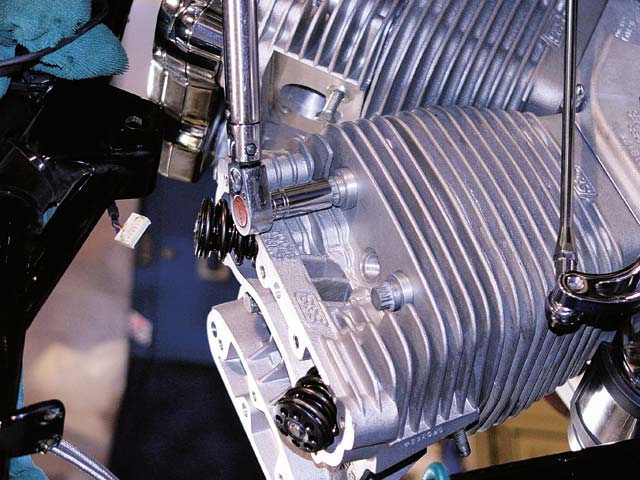
3. Leroy moved into the cam chest next, removing the ignition, lifter blocks, lifters, rotor, nose cone, and cam cover.
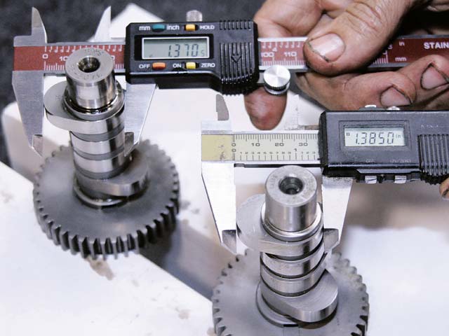
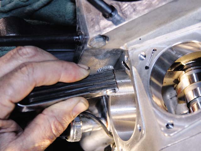
4. The original S&S; cam is smaller in every way, with a 0.560-inch lift, 252 degrees of intake duration, and 256 degrees of exhaust. Patrick Racing’s cam sports a 0.602-inch lift and 266 degrees of intake duration and 259 degrees of exhaust duration.
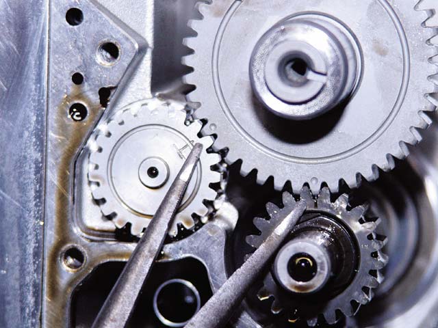
5. There are timing marks on the breather gear, crankshaft, and cam that must be lined up to properly install the cam. Keep the cam endplay between 0.005 and 0.050.
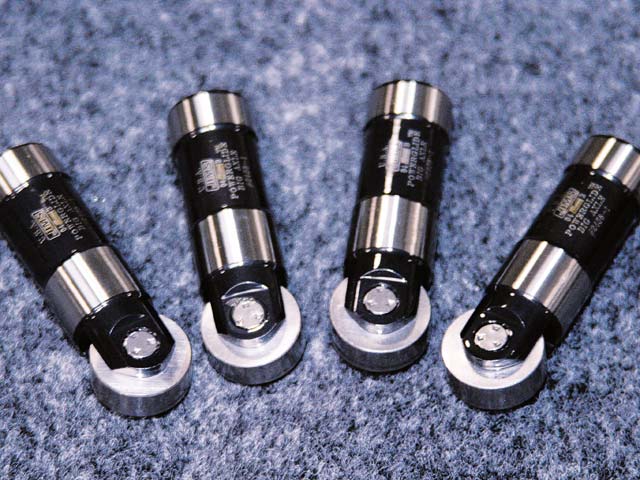
6. Whenever you swap out a cam, it is recommended that you get new lifters as well. Patrick Racing uses JIMS hydraulic roller lifters to reduce valve-train drag and noise.
7. A feeler gauge was used to check the endplay of the cam once it was secured in the cam cavity. Check your manual for your motor’s specific endplay value.
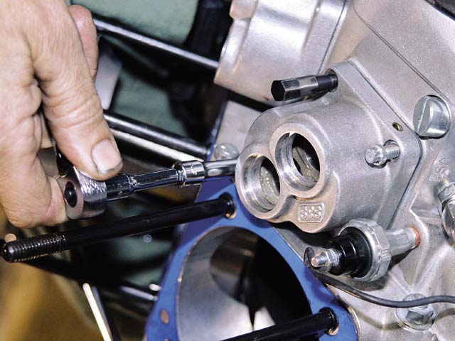
8. With a JIMS lifter block alignment tool and a fresh gasket, Leroy bolted the lifters to the case.
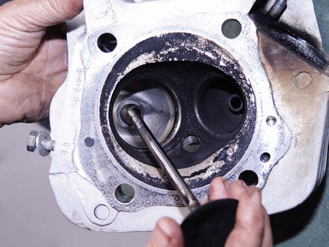
9. Before any porting could be performed on the head, the valves were removed, followed by…
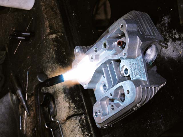
10. …the valve guides. The head was heated up with a torch to expand the valve-guide holes so the guides could be tapped out with a soft brass hammer.
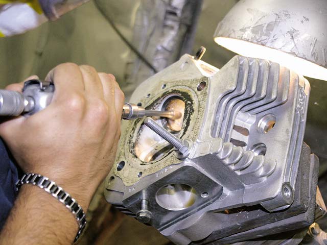
11. Porting the heads isn’t as easy as it looks — it takes a steady hand and an eye for aerodynamic detail to smooth the ports out properly and actually increase the airflow capacity. Experience is a big part of this: take too much out and you can reduce performance, if you don’t remove enough material, your time was wasted.
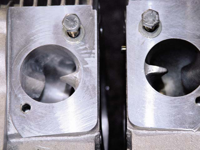
12. The intake port in the head on the left has been ported — all the flat surfaces, casting flash, and imperfections were reshaped to allow for more air and fuel to enter the combustion chamber.
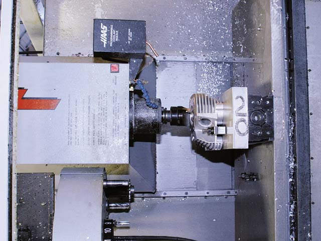
13. On the combustion chamber side of the head, Patrick Racing likes to clean up and resurface the gasket area with its in-house Haas CNC machine. 0.002 inch was removed.
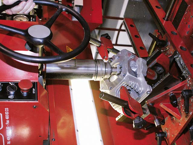
14. An extremely precise Serdi valve seat-cutting machine was used for cutting the valves seats. The blade used to cut the seats is actually tapered to improve flow and the pilot is self-centering. In other words, even if the head is mounted wrong, the Serdi machine will perfectly line up the valve according to the valve guide every time!
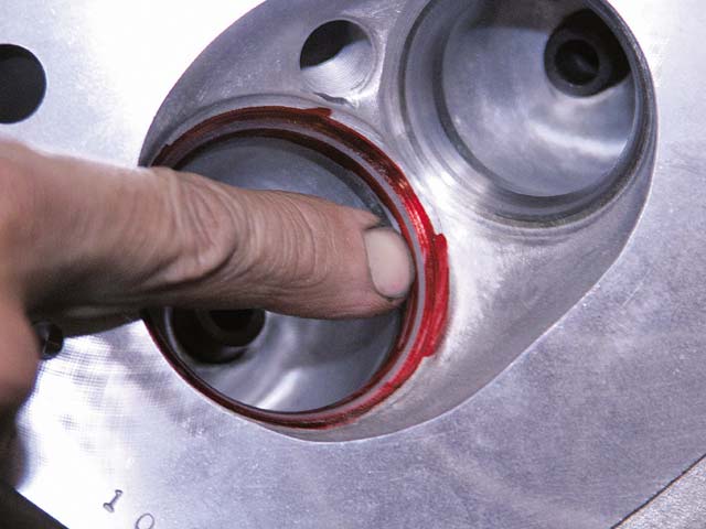
15. Valve lapping compound is like a fine grit liquid sandpaper. First, Leroy marked the valve seats with red marker, then he applied lapping compound to the valves. The valve is then reinserted into the valve guide and the valve is spun, by hand, against the seat. The red marker that is missing indicates the area that the valve contacts with the seat, if there is any area where none of the marker was removed, then the valve is not seating properly with the head. Our valve and seats were mated perfectly — a continuous ring of absent marker proved it.
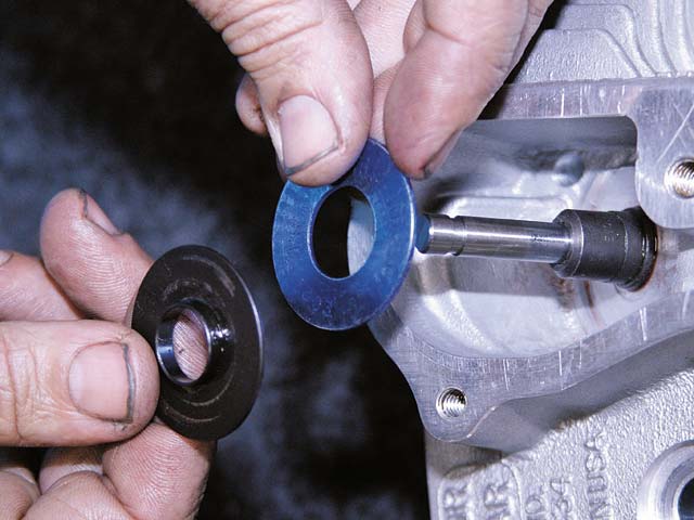
16. A spring shim was used to tighten up the valve spring and ensure adequate spring pressure by reducing the overall height. Then, the heads were reassembled with the addition of the original valves, springs, retainers, and keepers.
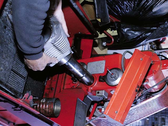
17. Whenever pistons come out of the cylinder, it’s always a good idea to re-hone the cylinder walls…
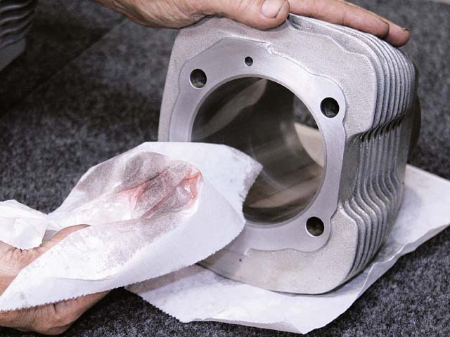
18. …and use a little oil and a clean paper towel to remove any residual particles from the honing stones.
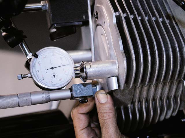
19. In order to deck (reduce the overall height) the cylinders and slightly raise compression, many measurements must be taken to make sure that the valves don’t interfere with the pistons when they are fully open. First, the gasket surface was cleaned on the cylinders and cases, a new gasket was installed, and the pistons were temporarily attached to the rods without rings. The cylinder was torqued down to the head with a set of special head bolts and aluminum spacers, and the thickness of the head gasket was measured at 0.050 inch. Then, the piston was brought up to TDC and the distance from the top of the piston to the top of the cylinder wall was measured at 0.0060 inch under the top of the cylinder (or deck).
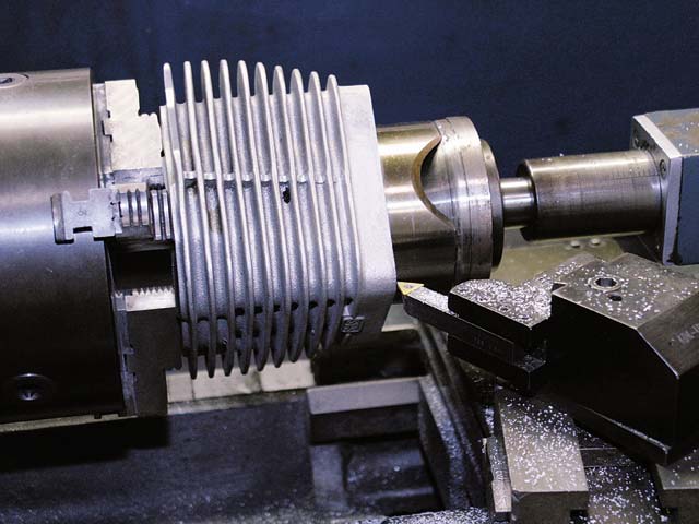
20. Nigel Patrick wanted to bring the piston up above the cylinder deck height, but not above the height of the cylinder and head gasket, in other words, about 0.030 inch above the height of the cylinder. The in-house lathe at Patrick Racing was used on the bottom of the cylinder (so the head gasket surface wouldn’t be damaged). The rod and piston relief was also slightly reduced and then beveled so the piston rings wouldn’t hang up during installation.
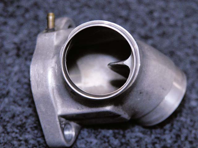
21. While the original design of the S&S; manifold works, Nigel knew the flow characteristics could be improved with a little porting.
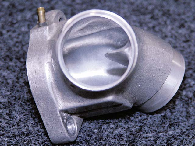
22. Just like the heads, the flat surfaces were removed along with the casting flash and any imperfections to smooth out the manifold to allow for more air and fuel to enter the combustion chamber.
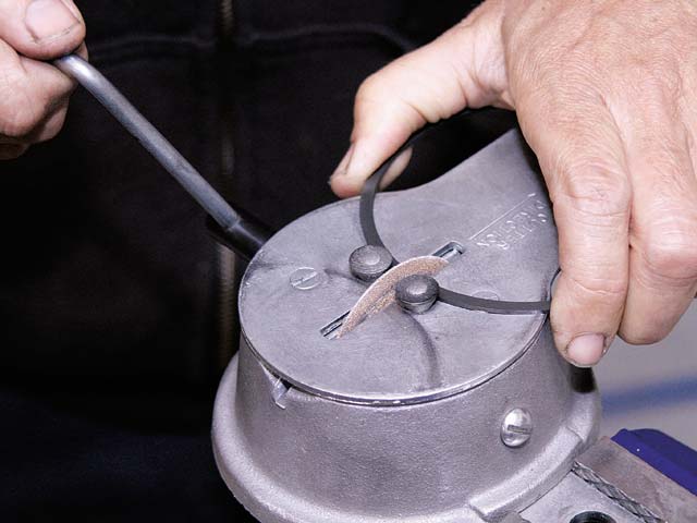
23. Piston ring gap for our 97-inch had to fall between 0.0150 and 0.020 inch. A hand-driven piston ring grinder was used to bring the rings within specs.
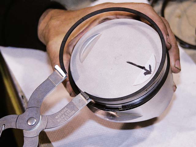
24. Piston ring expanders opened up the rings enough to slide them over the piston without damaging the aluminum, and all the ring gaps were spaced approximately 90 degrees from one ring to the next.
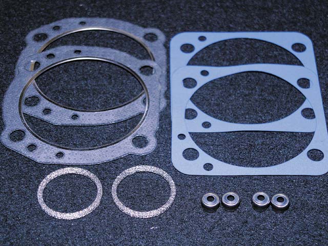
25. Final installation required a new set of S&S; base, head, and exhaust gaskets.
26. The pistons were installed on the rods, and the cylinders were slid over the pistons. The heads were then torqued onto the cylinders according to the manual specifications.
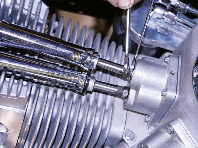
27. All four pushrods were slid into place before the rocker boxes were secured. The pushrods were then adjusted to the new shorter overall height from the lifters to the rockers.
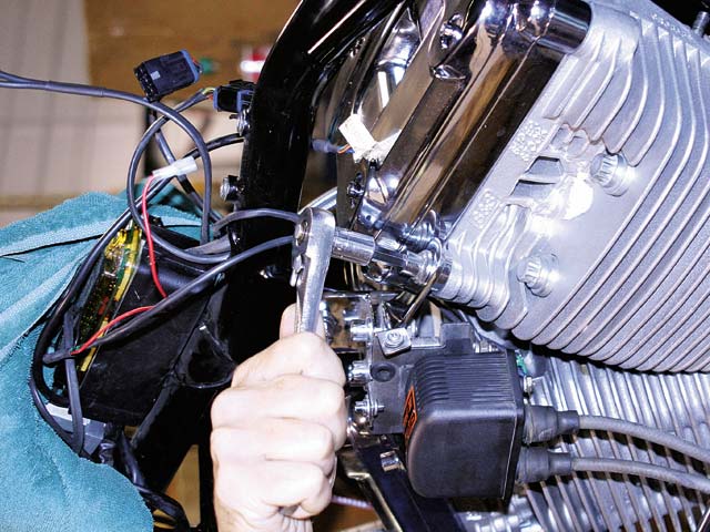
28. After the manifold and carburetor were installed and the motor was completely bolted back together, the top mount and ignition coil were bolted back onto the bike, followed by the tanks and dashboard. As soon as the new piston rings were seated in the cylinders, it was time for the fun part: some dyno runs!
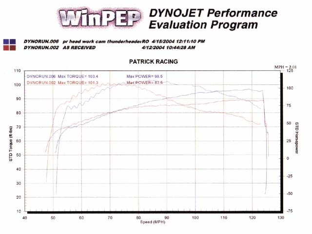
29. The numbers speak for themselves. While there was a minimal torque gain of about 2 lb-ft, there was a huge gain of 15 hp, a 12.5 percent increase!
It shouldn’t take you long to figure out why we wanted to do this article — we wanted more power! There are many ways to improve performance on a V-twin motor, but we wanted to try and use as many of the original components as possible while still making a significant gain. We brought our ’01 Titan, sporting an almost stock 97ci S&S; motor, over to Nigel Patrick’s shop in Garden Grove, California, to see what he could do to wake up our motor. After a brief consultation, Mr. Patrick decided that some head and manifold porting, a slight bump in compression, and a special Patrick Racing grind cam would definitely improve the peak performance for the motor. The only part we’d be swapping out would be the cam — everything else Patrick changed was simple modifications the stock components. Keep in mind the 97ci motor is the basis for the 113ci and 124ci motors, so this performance upgrade applies to more than just the 97!


