
Twin Cam Valve Job
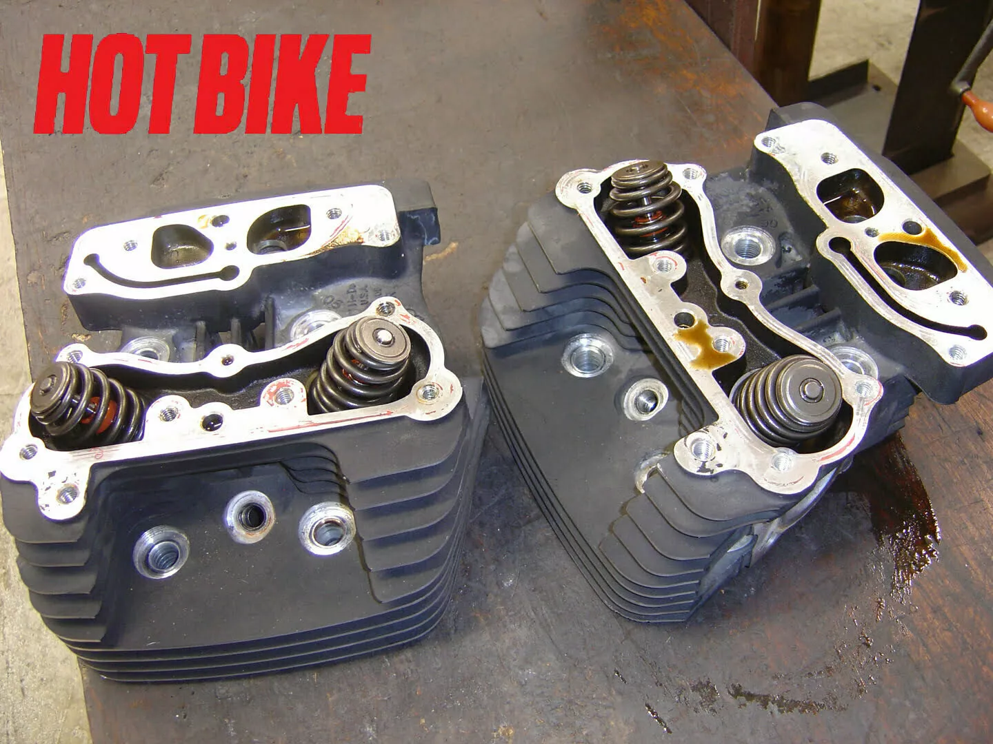
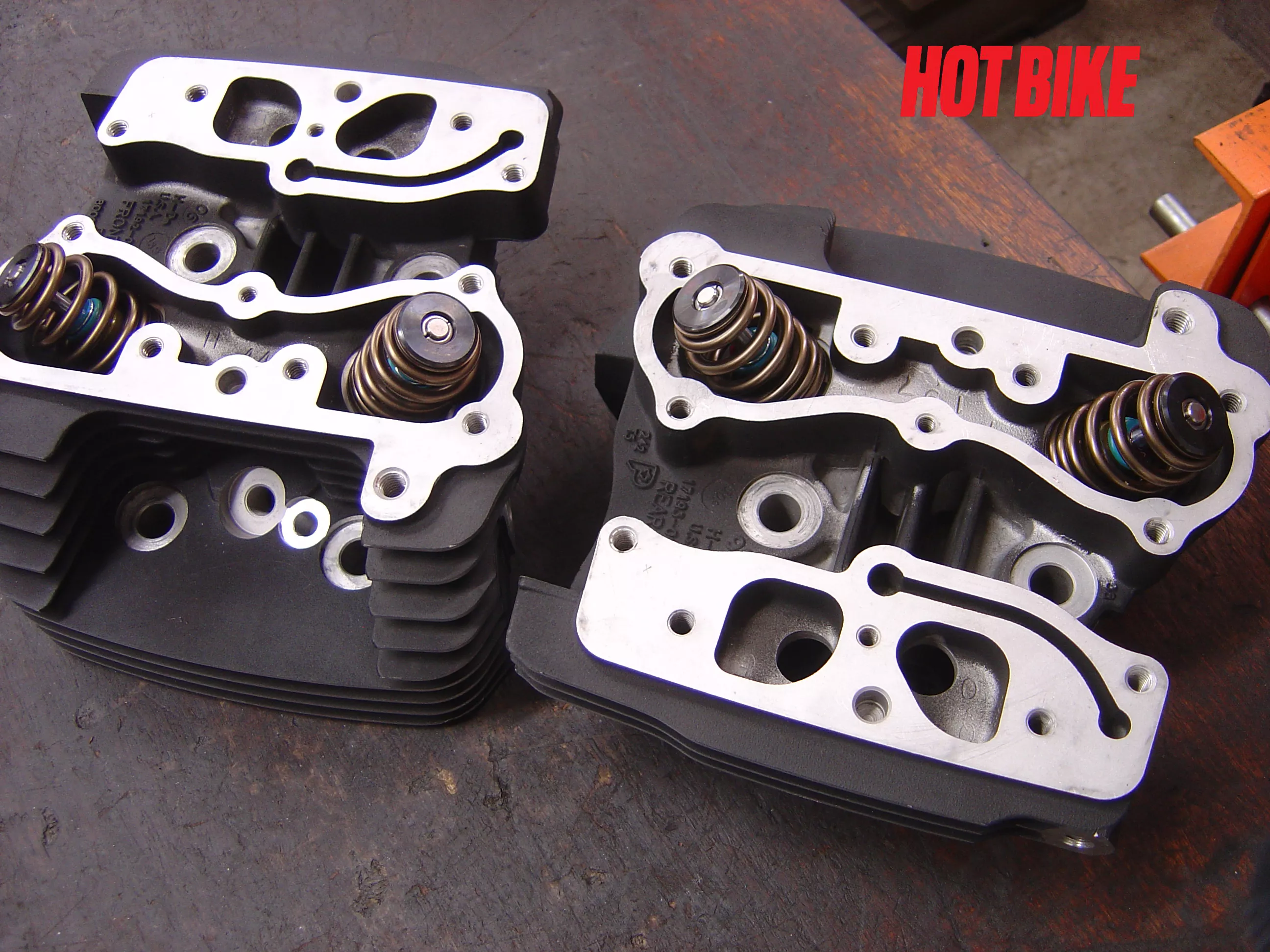
- Twin Cam heads ready for tear down.
Text And Photos: Bob Colvin
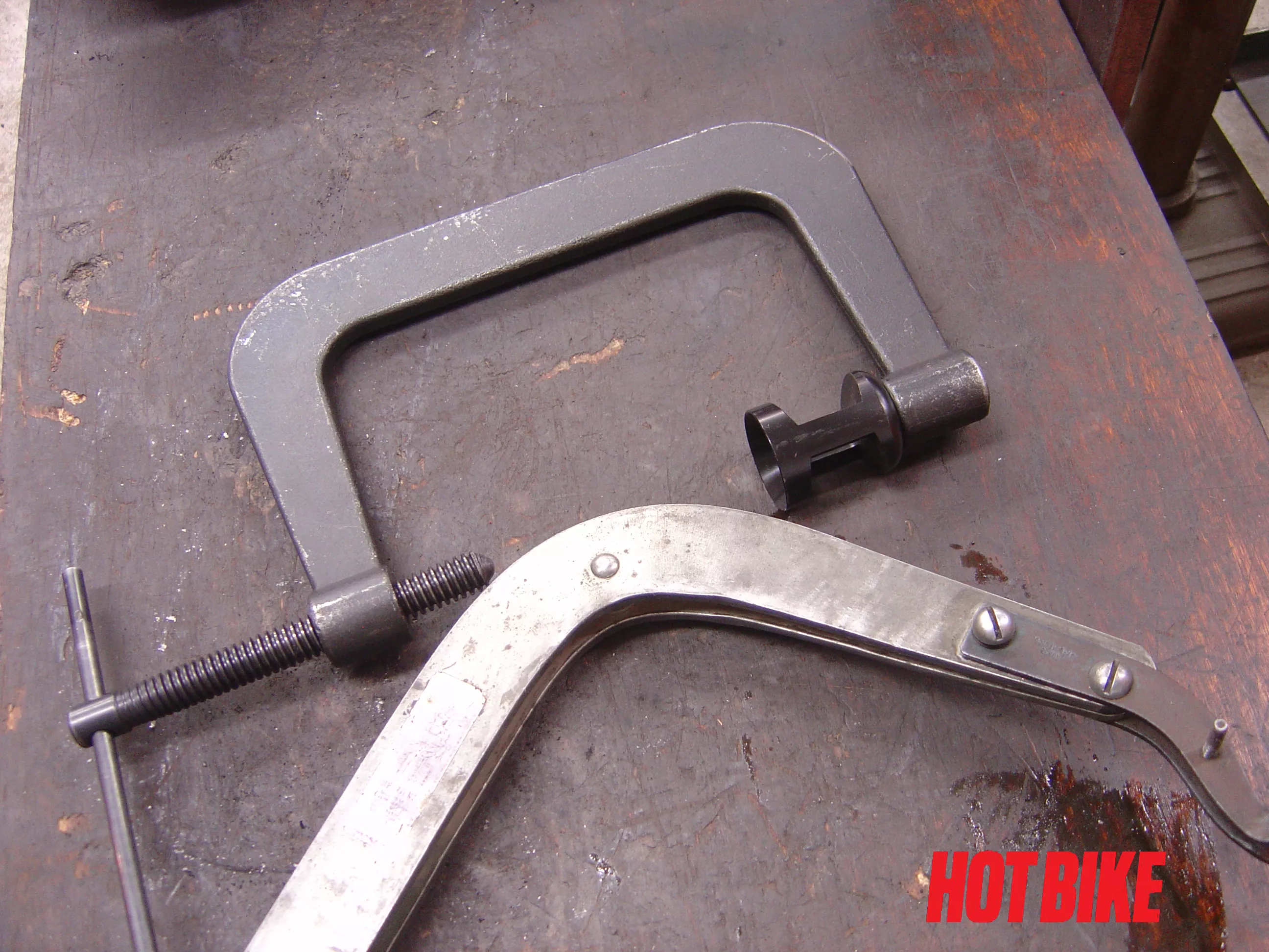
- Valve spring compressors. Notice the screw type has the adaptor for the smaller retainer on beehive springs. The lever type jaws are adjustable. Both work well
Text And Photos: Bob Colvin
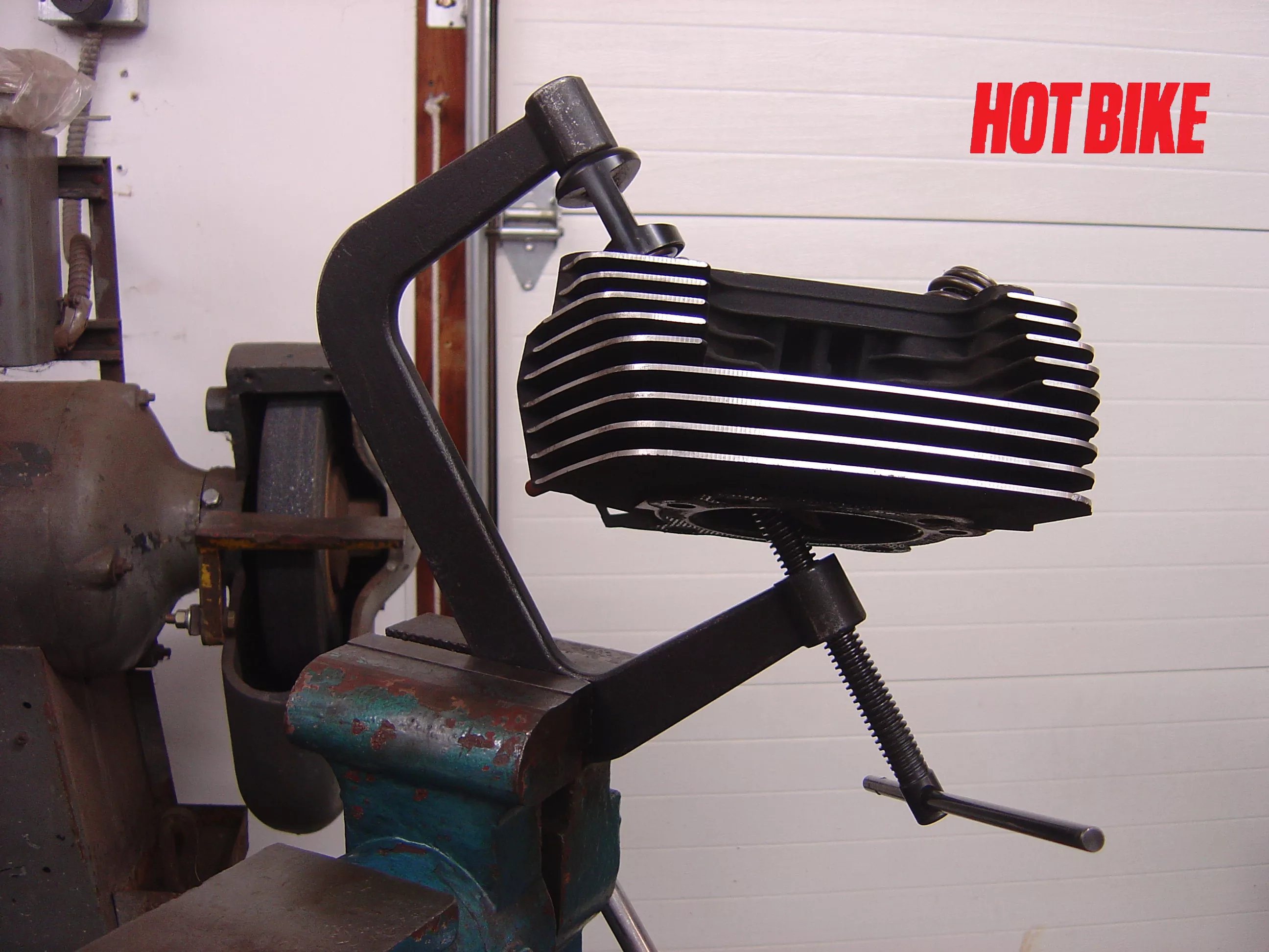
- Clamping the c-clamp type of compressor in a vise frees up your hands. This type of compressor works really well when installing high-pressure valve springs.
Text And Photos: Bob Colvin
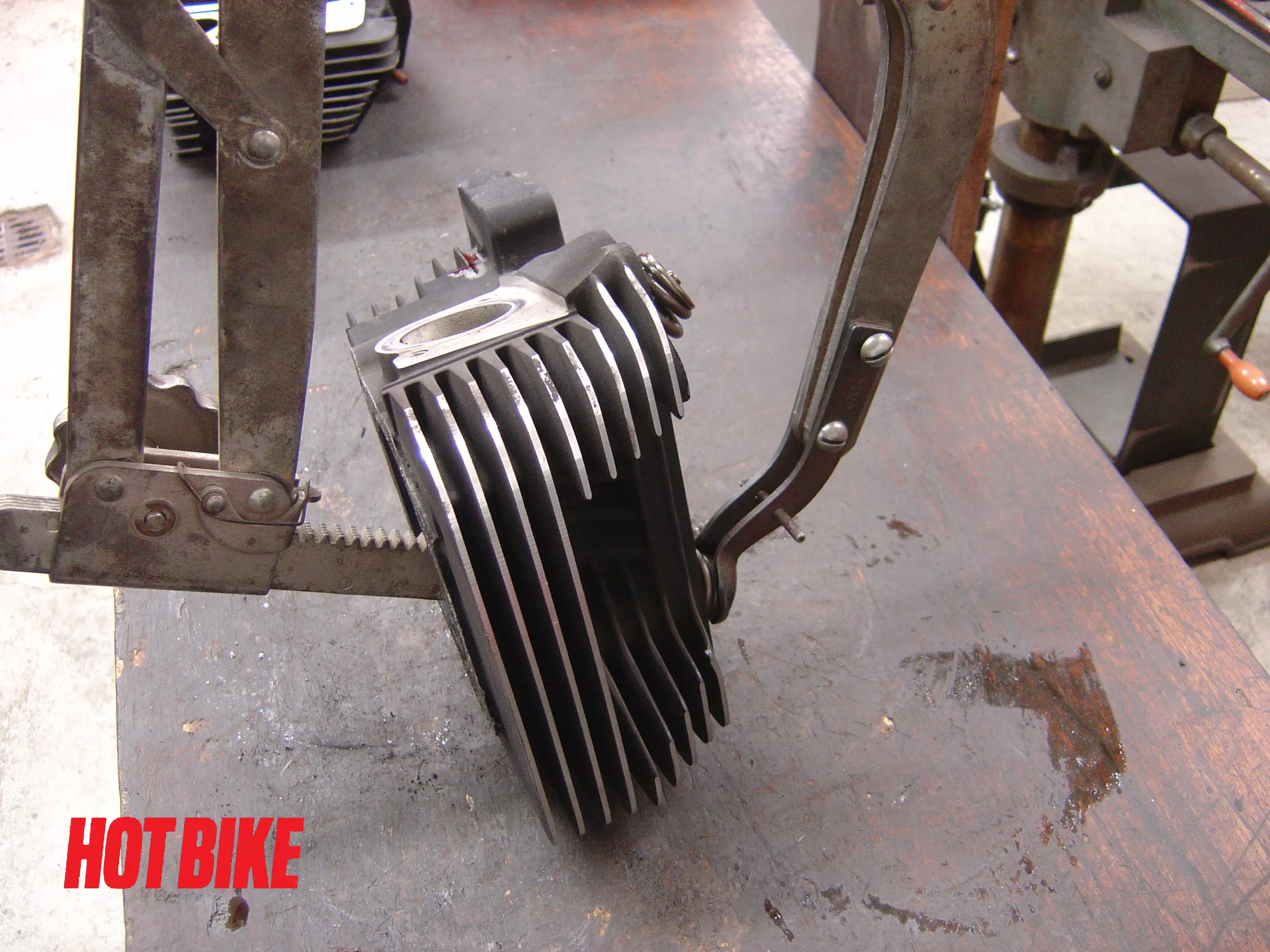
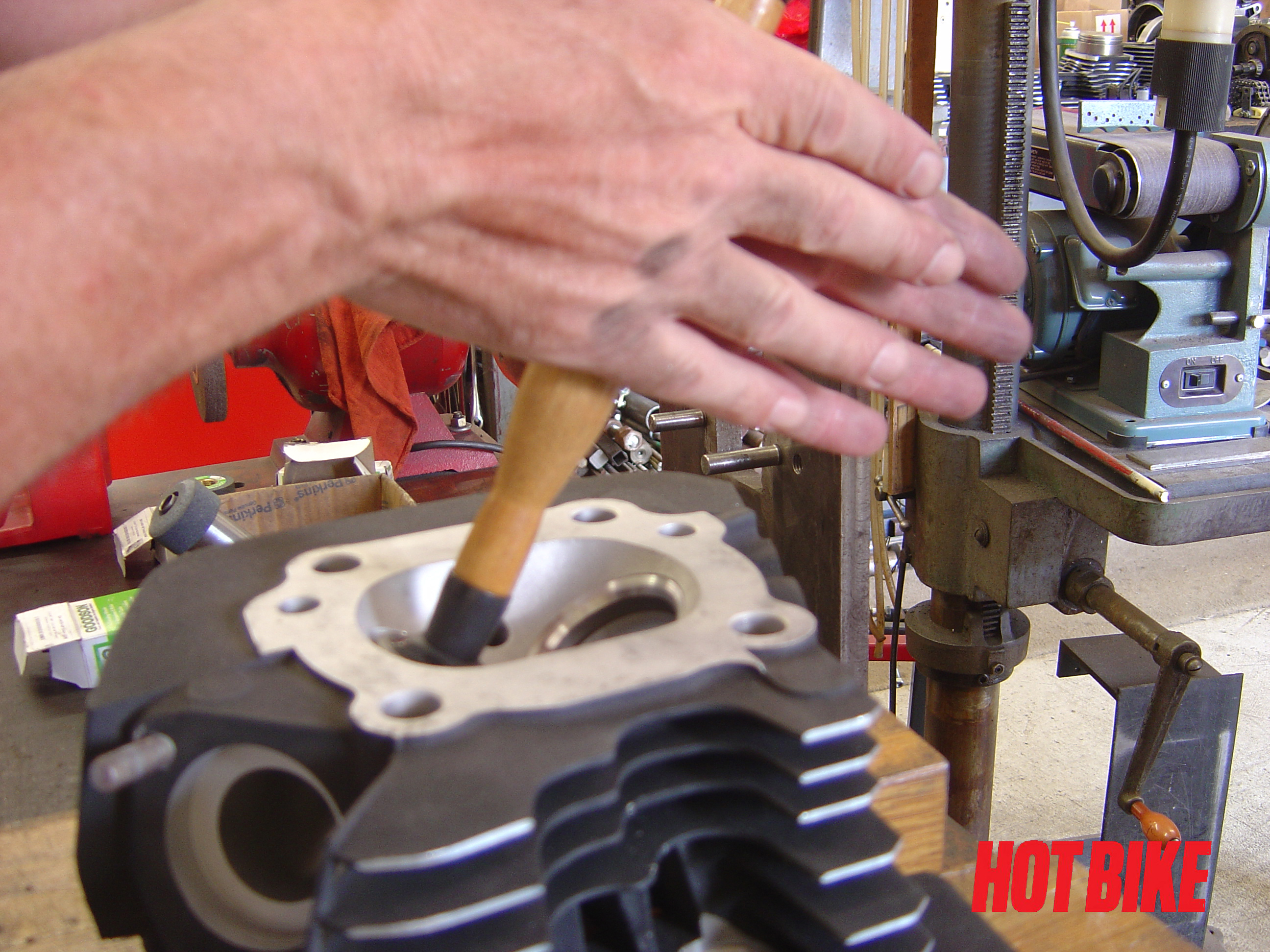
- Having done this a few times, we used the lever type spring compressor and balance the heads on the teardown bench. Always maintain control of the head to prevent any chance of damage.
Text And Photos: Bob Colvin
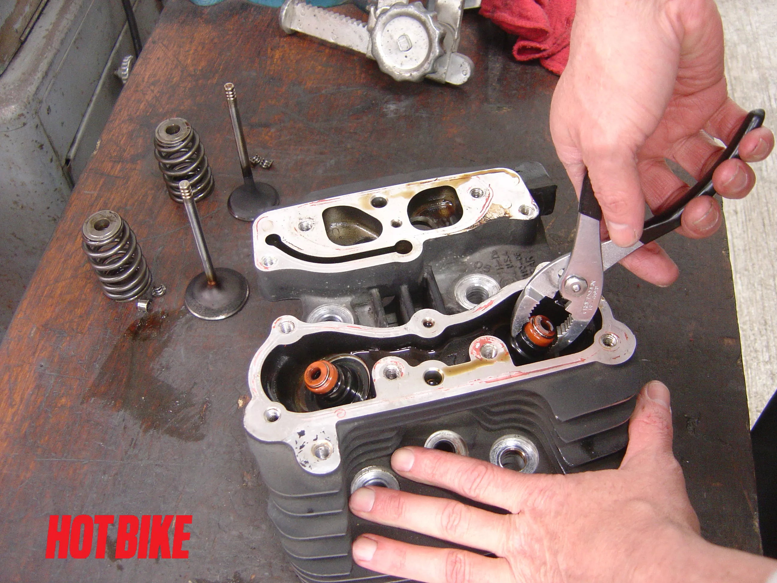
- Once the valves and springs were removed, we used a pair of pliers to pull the valve seals off.
Text And Photos: Bob Colvin
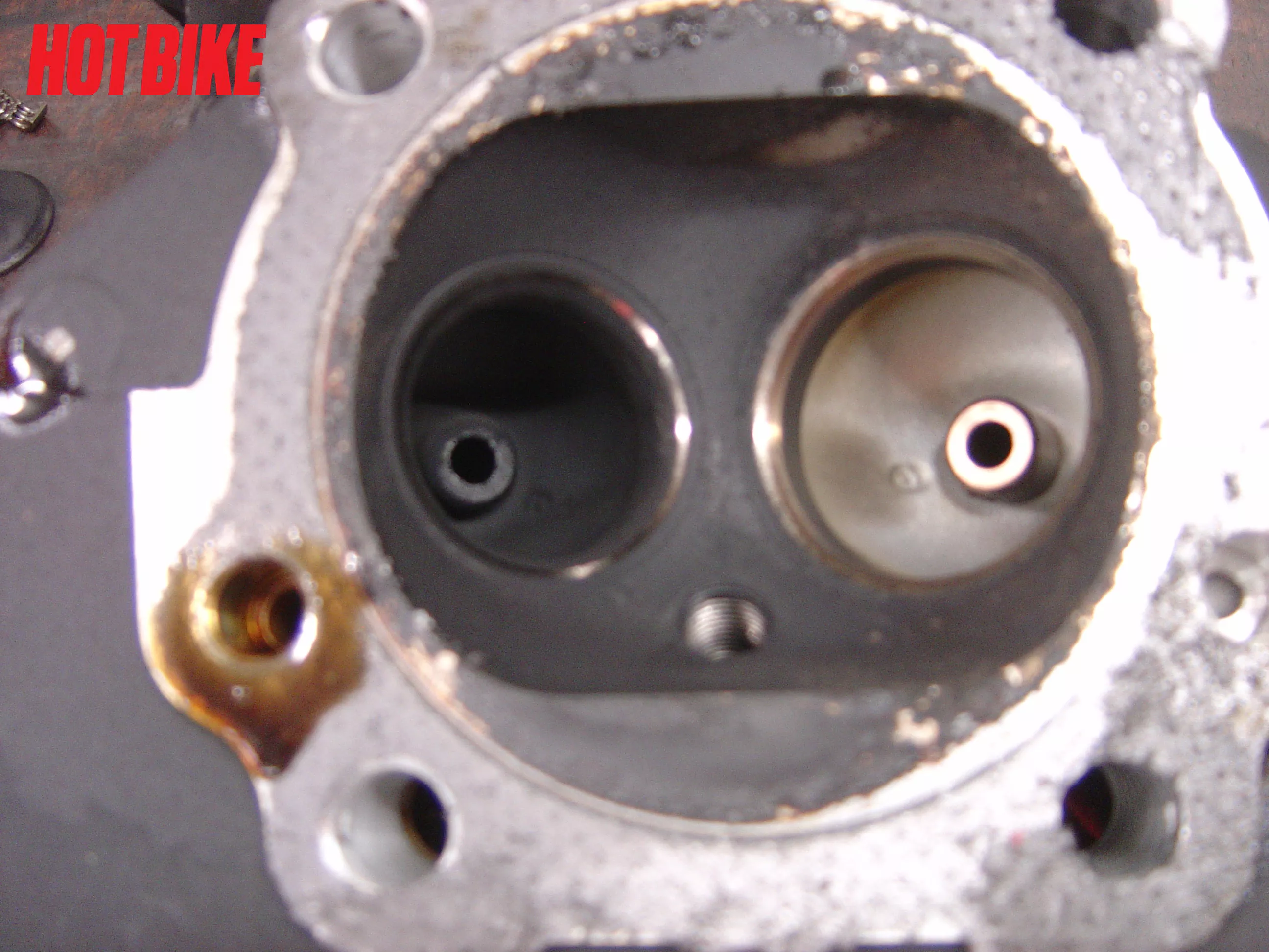
The combustion chamber and exhaust port are full of carbon. This can cause all sorts of problems, including pre-ignition.
Text And Photos: Bob Colvin
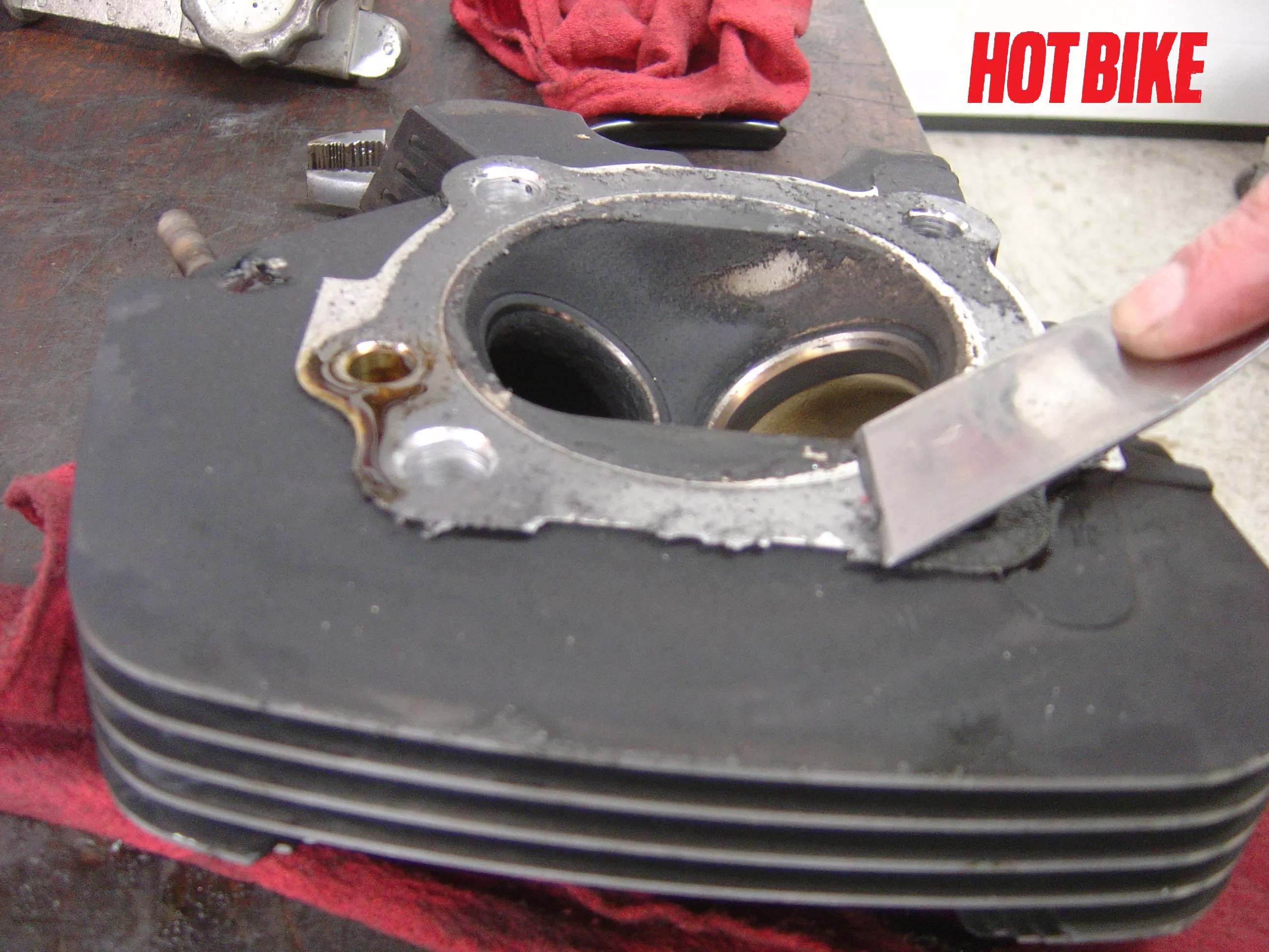
- Using a gasket scrapper we knocked off the big pieces of left over head gasket.
Text And Photos: Bob Colvin
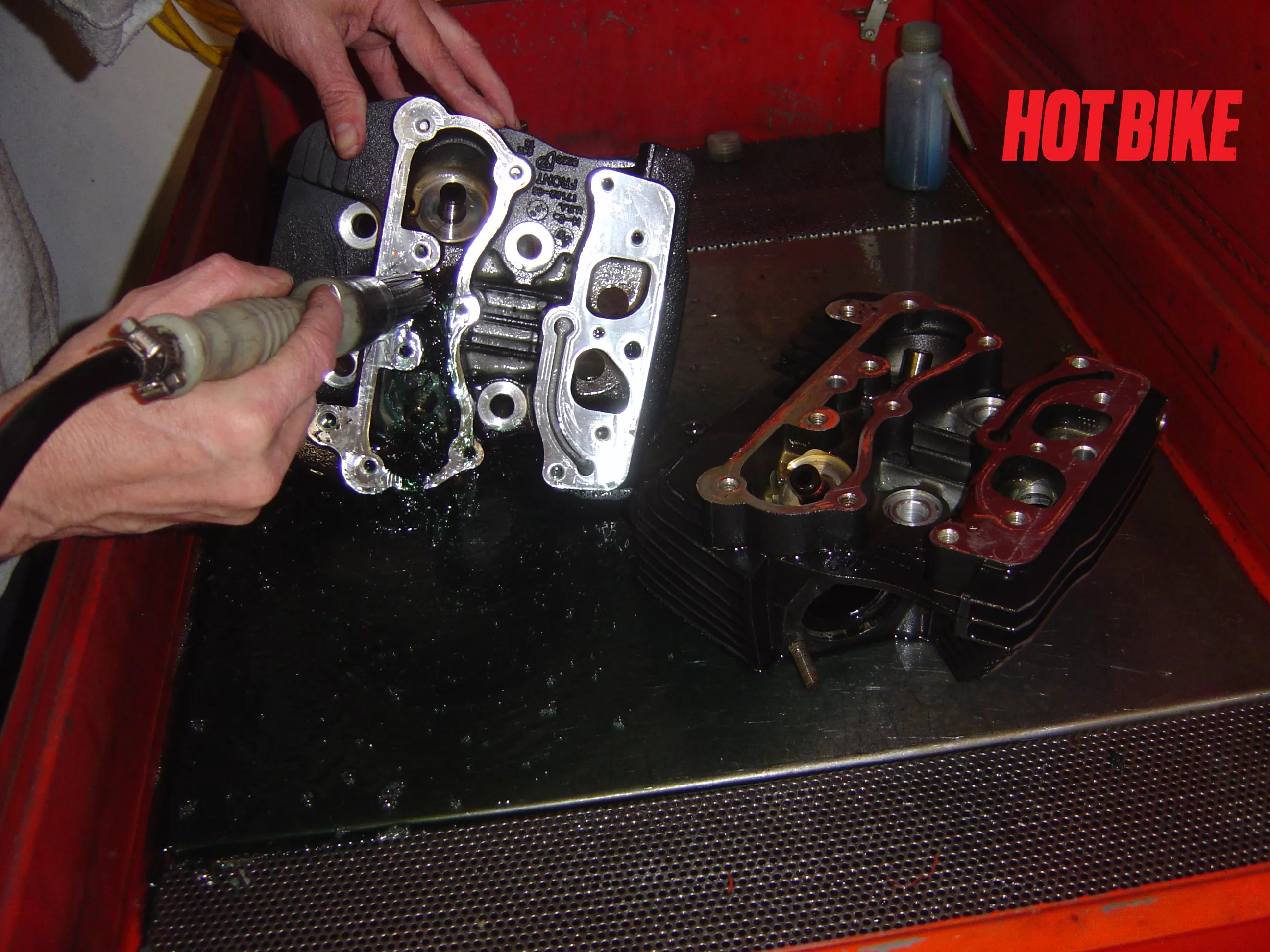
- Next into the wash tank. The goal is to remove as much oil and debris as possible. Any oil remaining can hold glass beads, which could be released into the motor after reassembly or prevent correct torque when installing rocker boxes and intake manifold.
Text And Photos: Bob Colvin
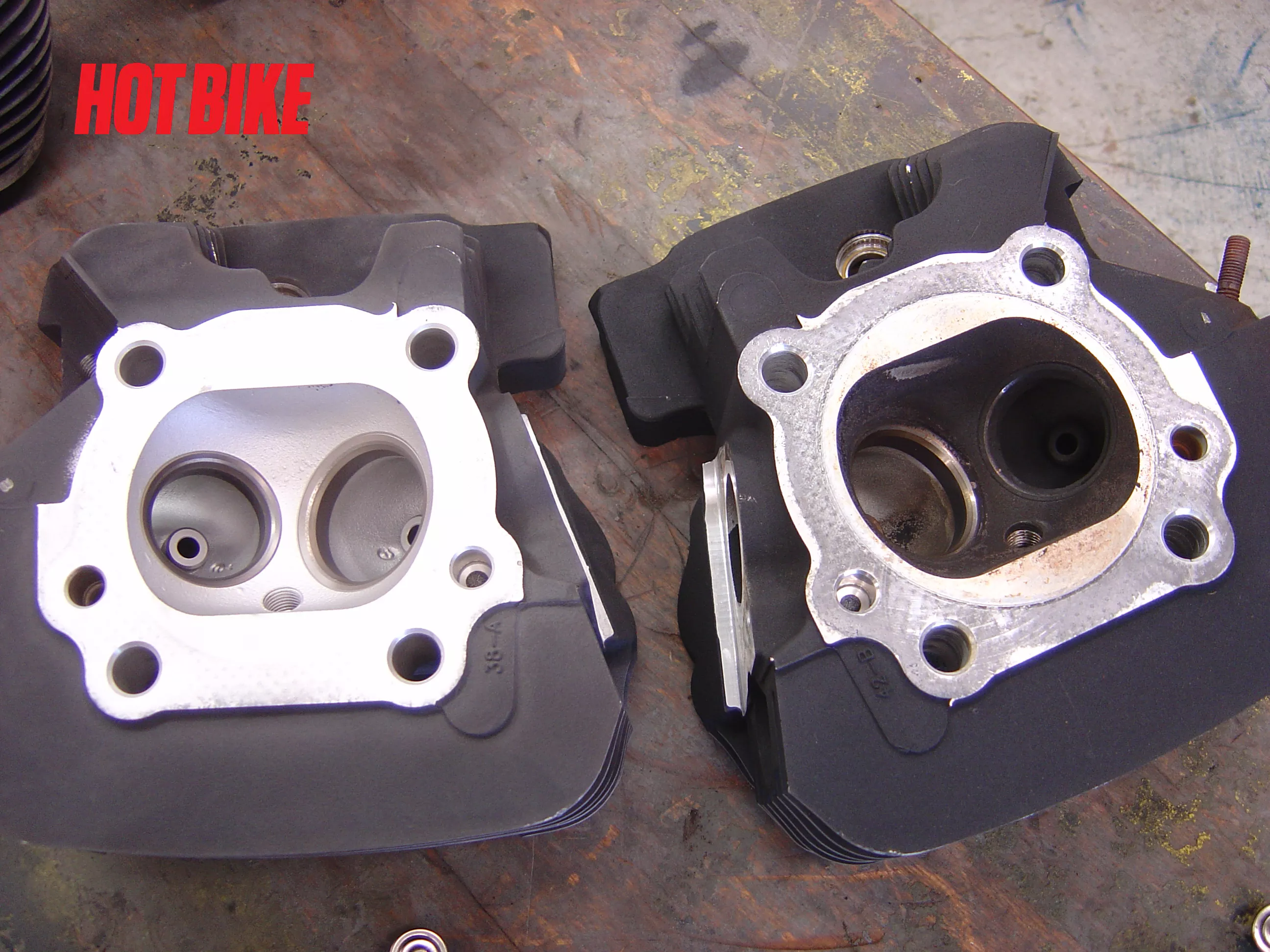
- The head on the left is fresh out of the glass bead cabinet. Nice and clean just the way we like it.
Text And Photos: Bob Colvin
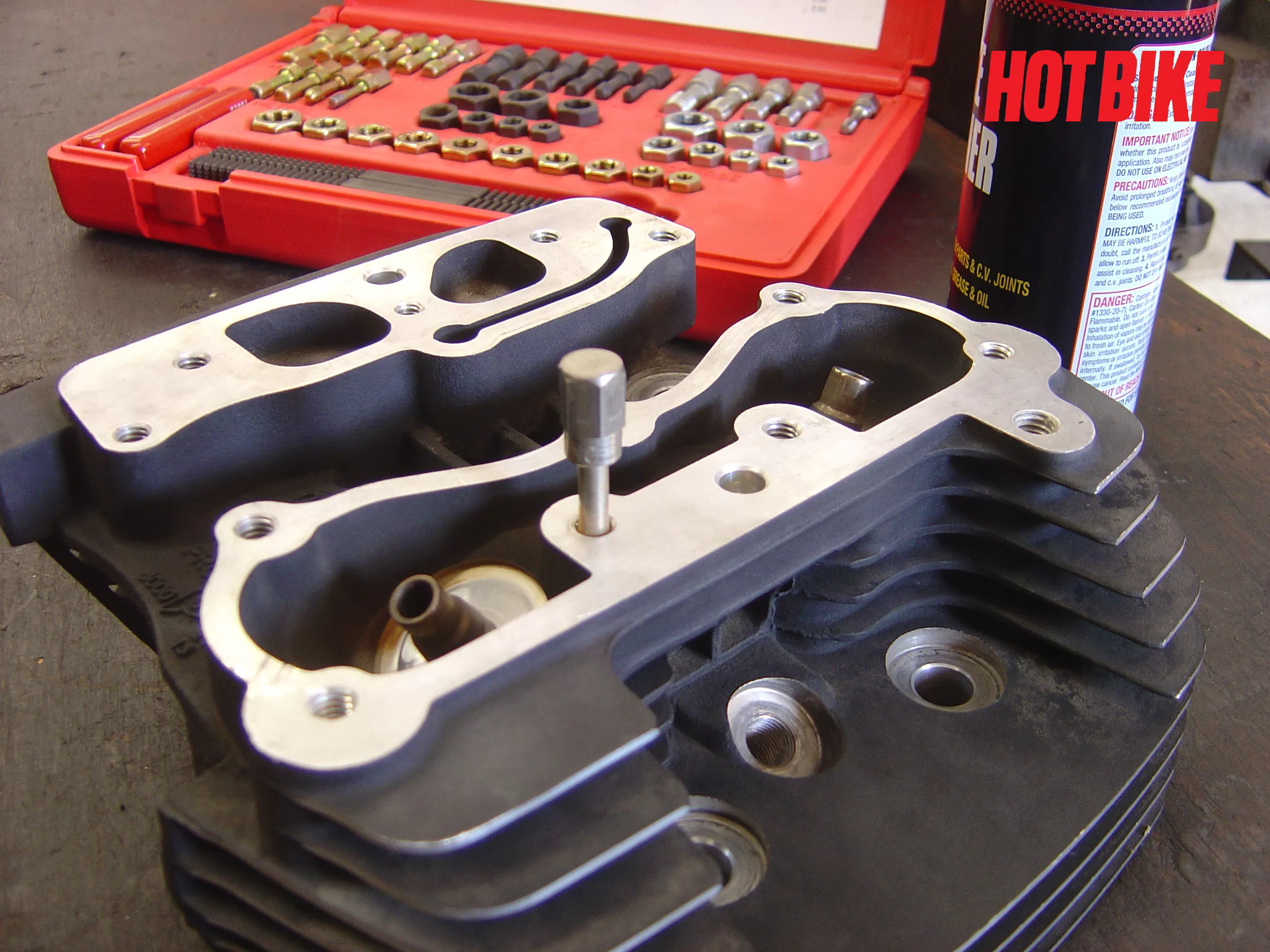
- Using brake clean, thread chasers, and compressed air we cleaned out of the bolt holes. Always wear eye protection when working.
Text And Photos: Bob Colvin
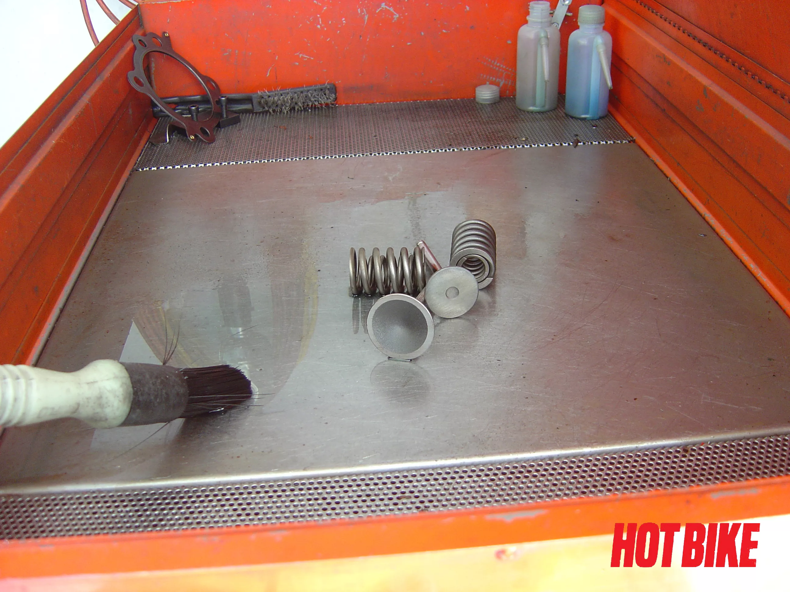
- Valves, springs, retainers, and keepers were cleaned in the wash tank.
Text And Photos: Bob Colvin
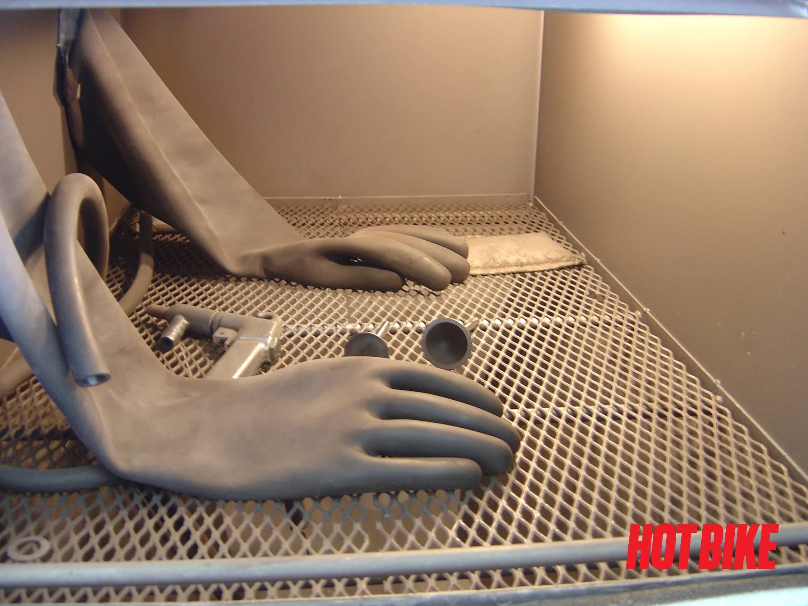
- The valves also go into the glass bead cabinet for cleaning the carbon off the valve head. Some valves have hard chrome-plated stems. Cover the stems and only clean the valve head.
Text And Photos: Bob Colvin
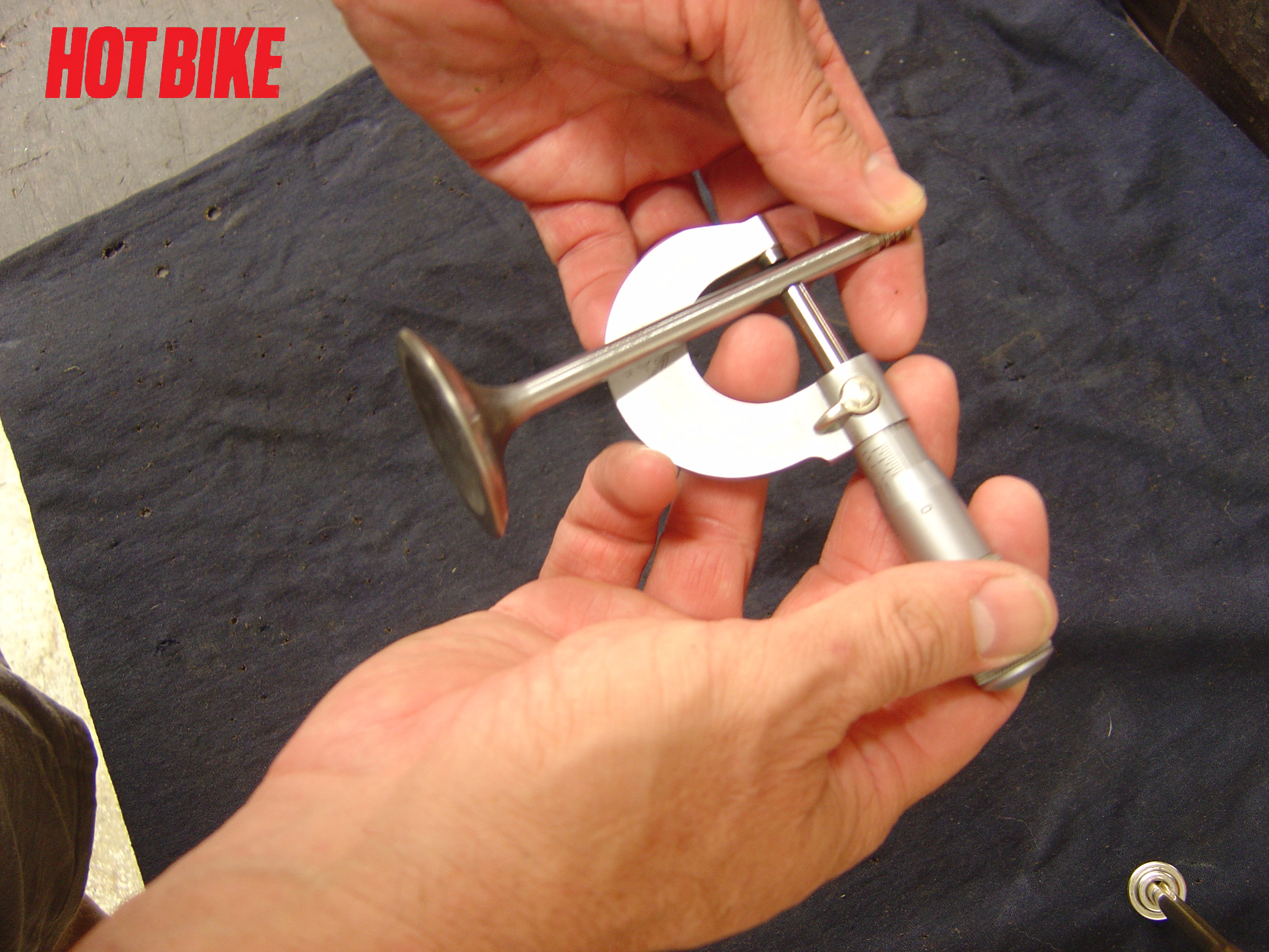
- Now we start inspection. Valves stems are checked for wear. Three places up and down then again at 90 degrees. The diameters are noted.
Text And Photos: Bob Colvin
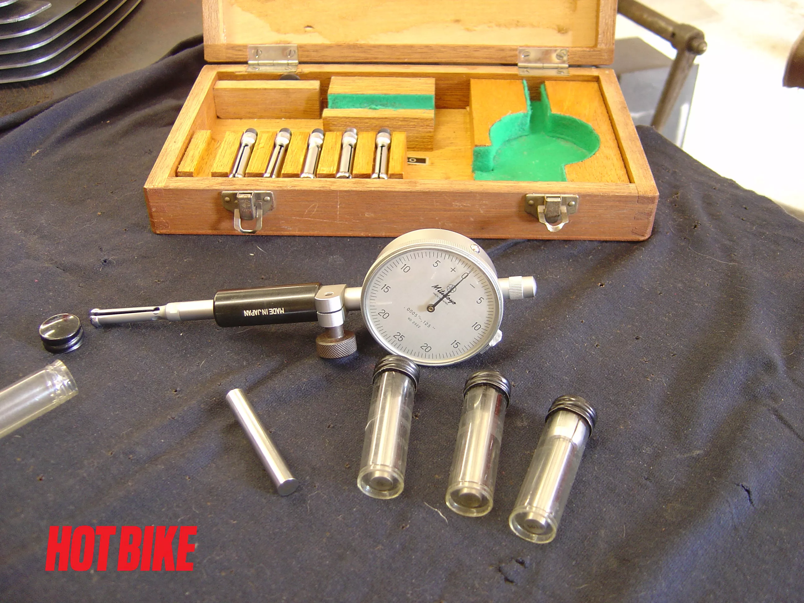
- For checking valve guide inside diameters, you can use pin gauges. These come in half-thousand sizes and are very accurately ground. A bore gauge is another option setup that takes a little more work, but the direct readout makes checking the guides faster.
Text And Photos: Bob Colvin
- Starting with a pin gauge .0005 over the valve size, we checked the guides increasing pin size until finding the largest pin that would fit. Checking the factory manual the clearances for intake valves were .0008–.0035. Exhaust valves were .0015–.0036. We think the max values are way too big. Clearance on intakes we like at .0015 or less and exhaust at no more than .002. Unless you’re building a rat bike and want it to tick. Exceptions are made for drag motors. Follow the valve/guide manufacturer’s recommendations. Subtract the valve diameter to calculate clearance.
Text And Photos: Bob Colvin
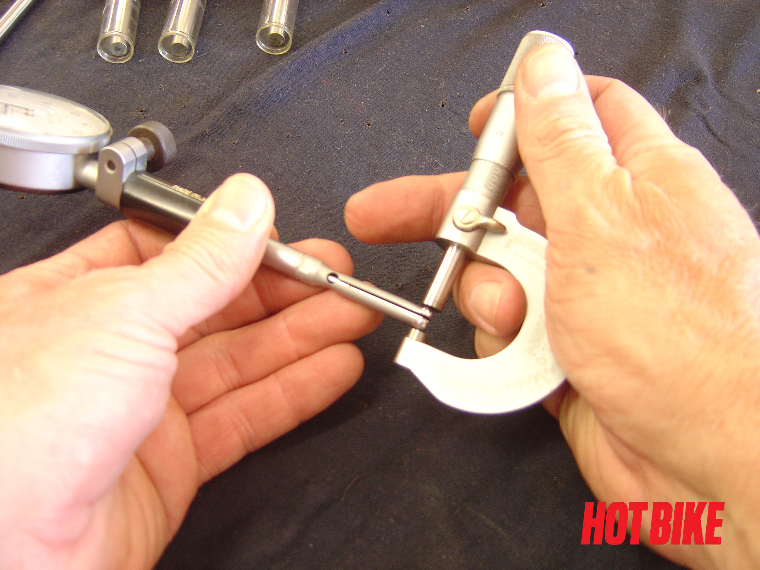
- If using a bore gauge, set the mic to valve diameter and zero the bore gauge.
Text And Photos: Bob Colvin
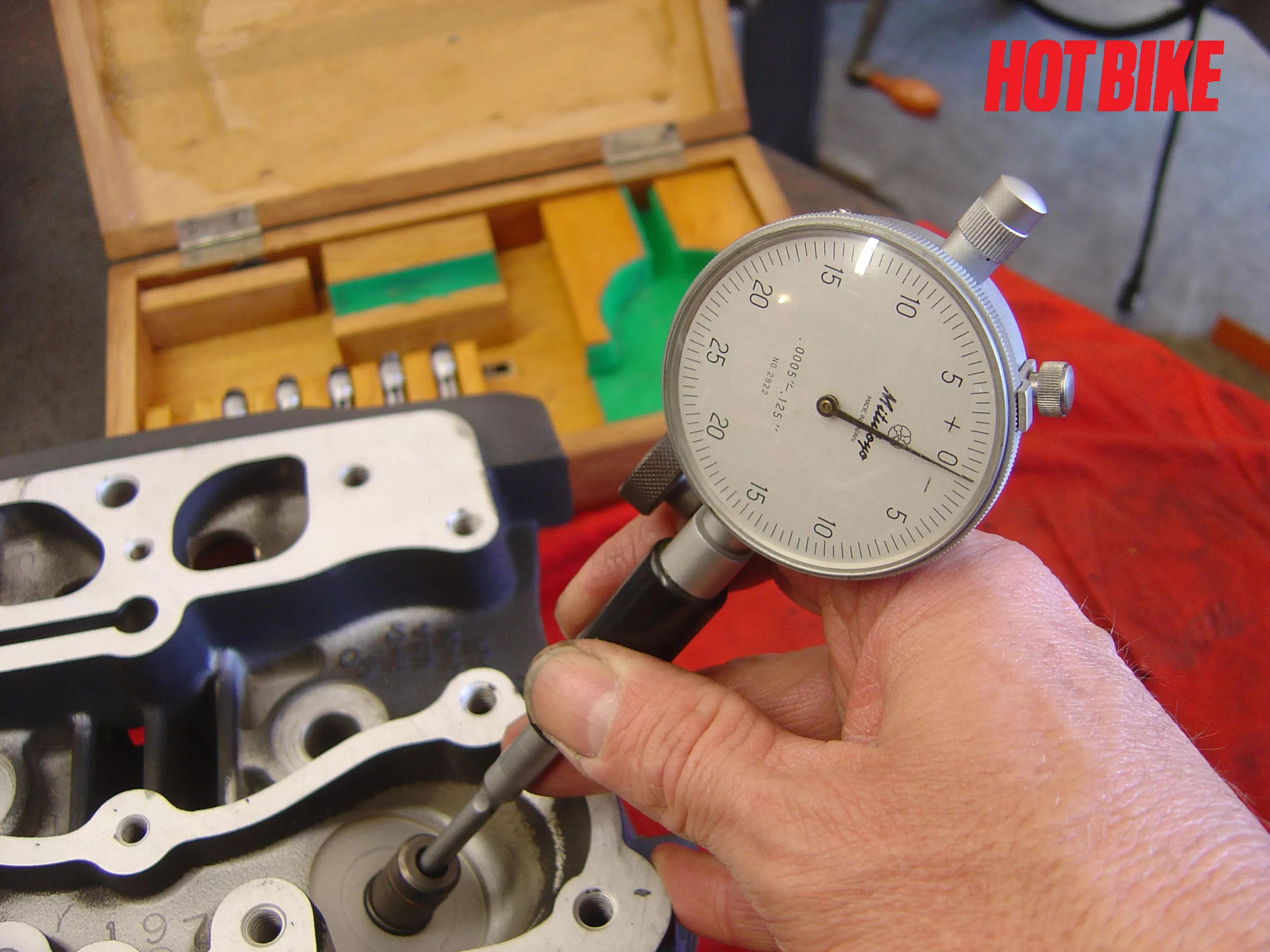
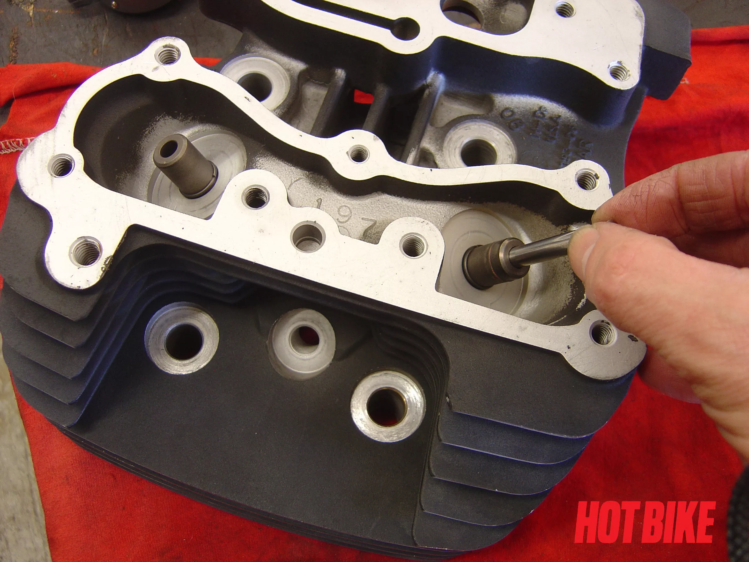
- Insert gauge into valve guide checking full length. Valve guide clearance was just over minimum spec. No need to replace valves or guides on this job.
Text And Photos: Bob Colvin
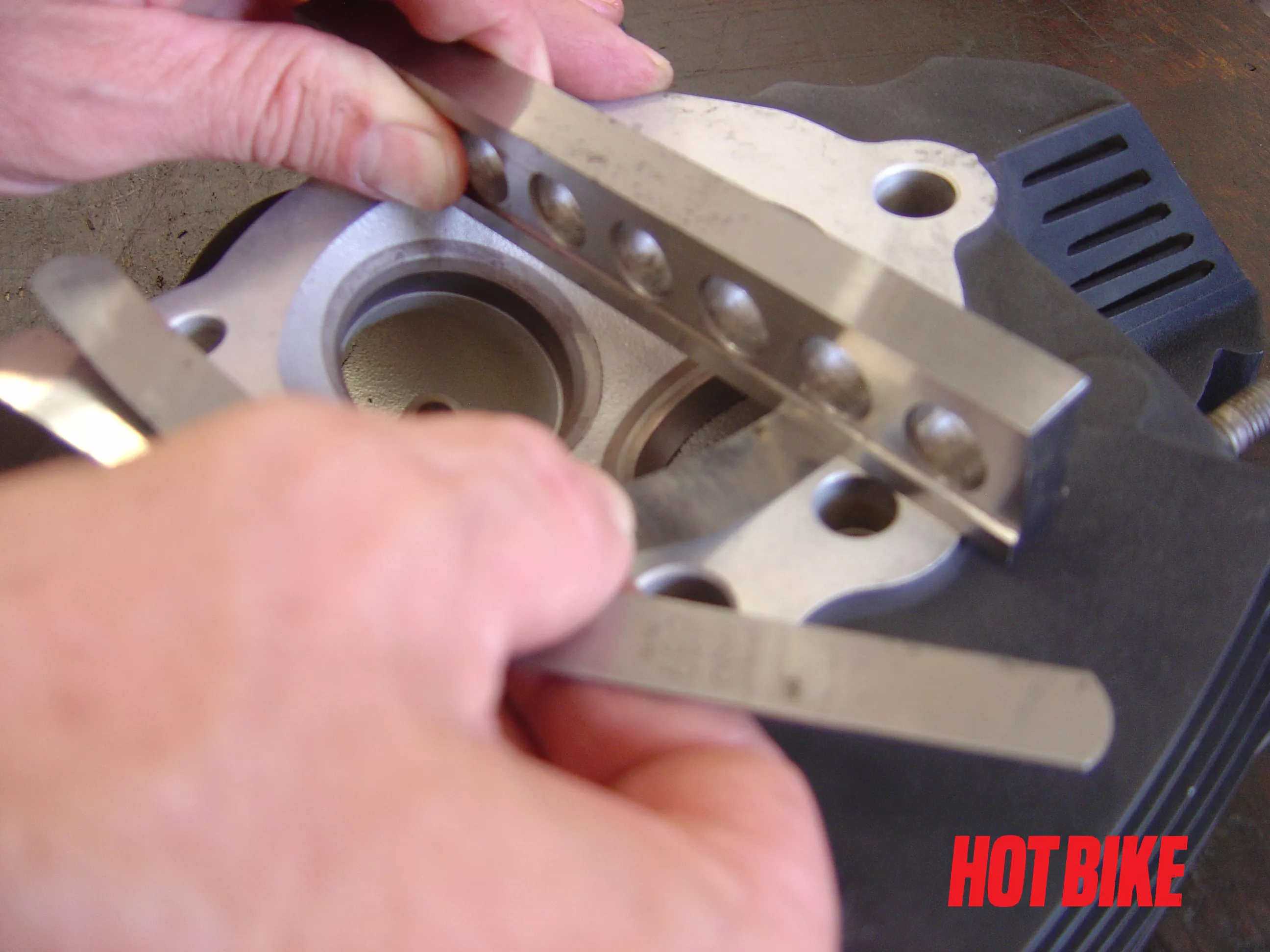
- Head gasket surface is checked for warpage using a straight edge and feeler gauge.
Text And Photos: Bob Colvin
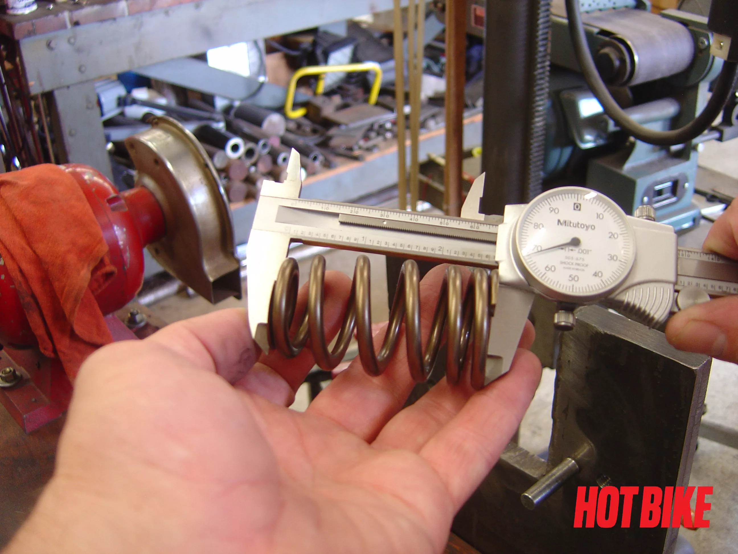
- One more check is valve spring free length. With only 20K it’s not likely a problem, but if overheated a few times, the springs could be sagged and weak.
Text And Photos: Bob Colvin
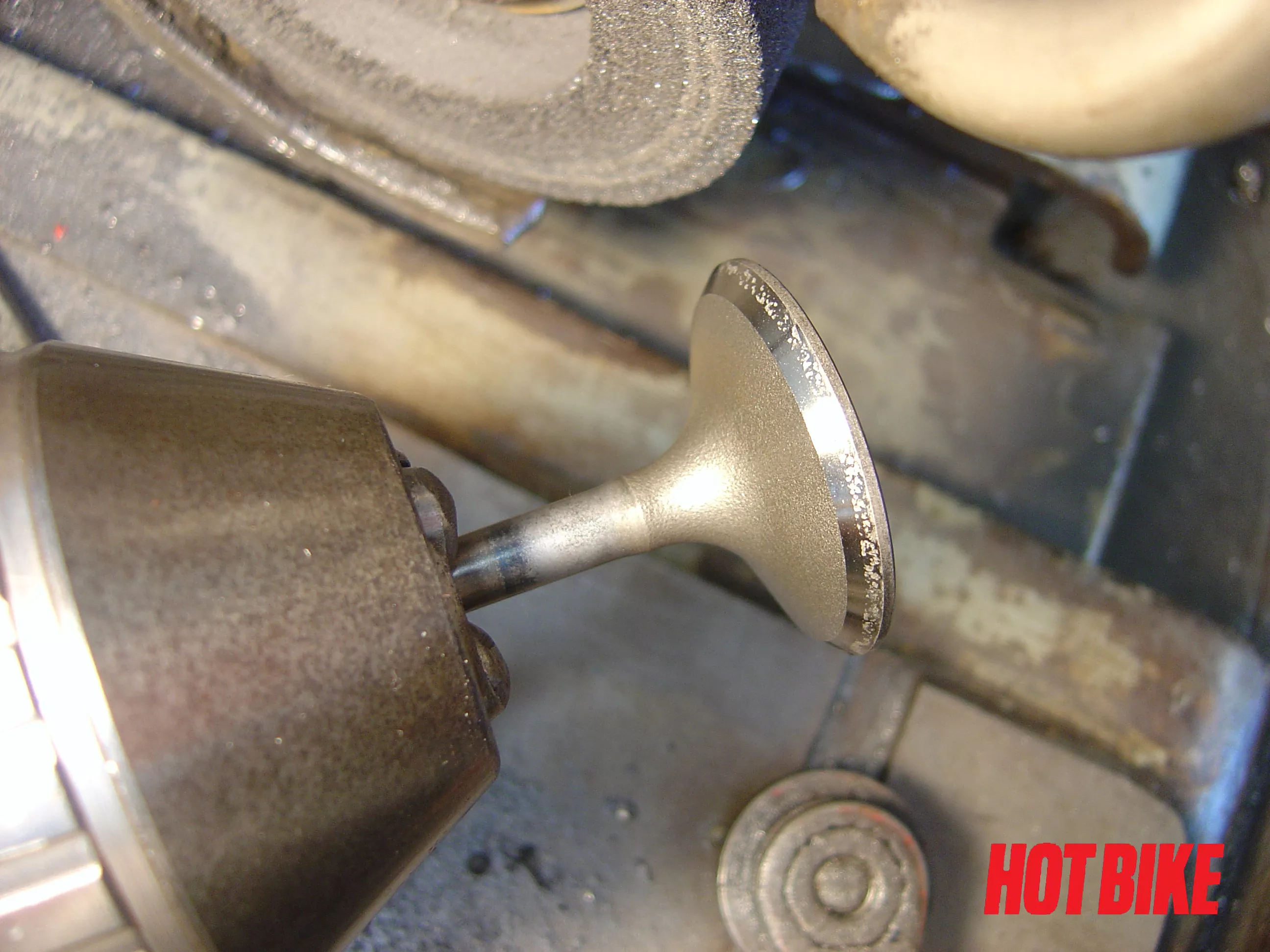
- The valves were ground to clean up the face. Notice the pits in the exhaust valve face, and this is with less than 20,000 miles on the engine.
Text And Photos: Bob Colvin
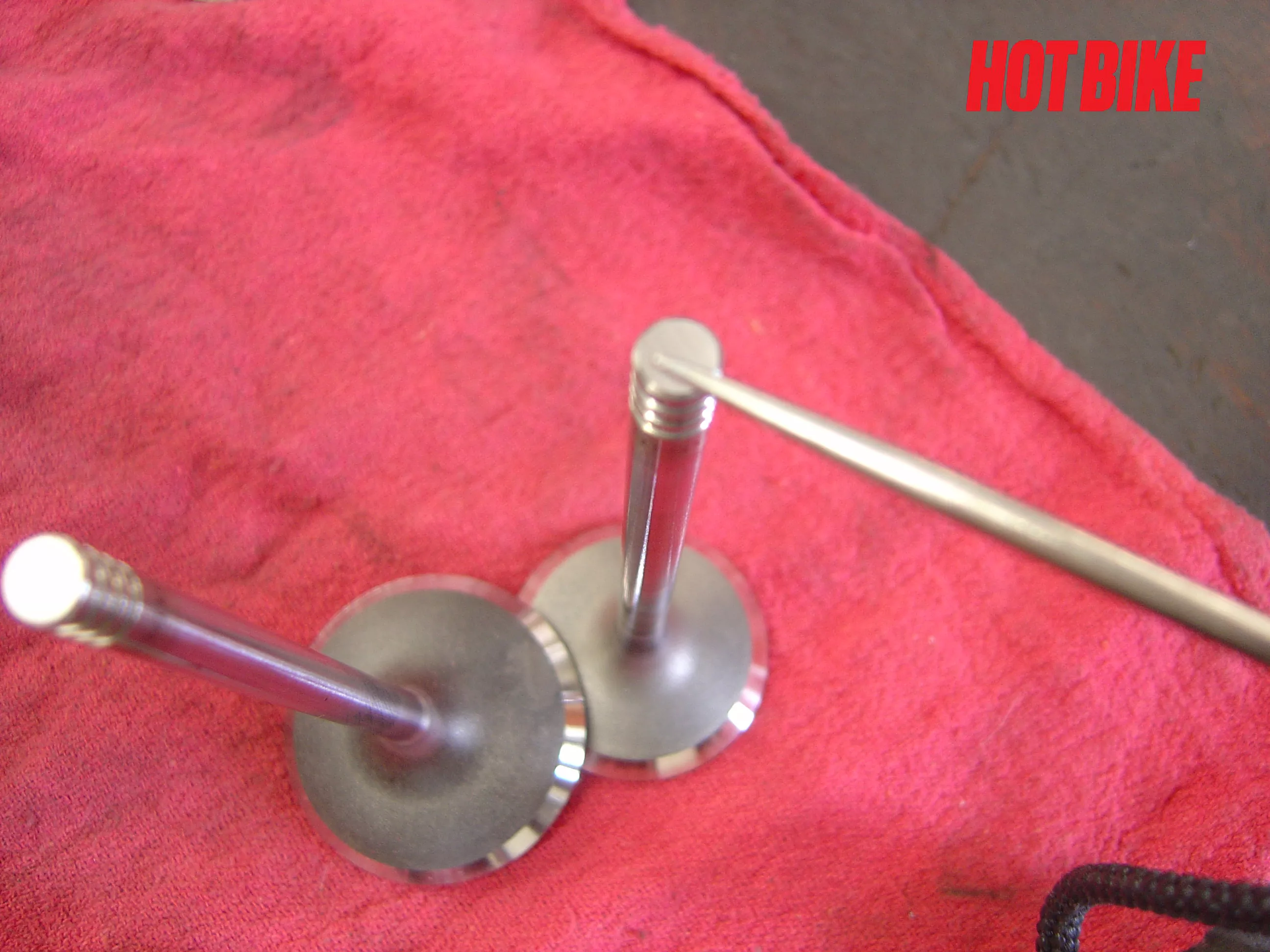
- The ends of the stems are also ground. This removes wear and squares the end to the valve stem.
Text And Photos: Bob Colvin
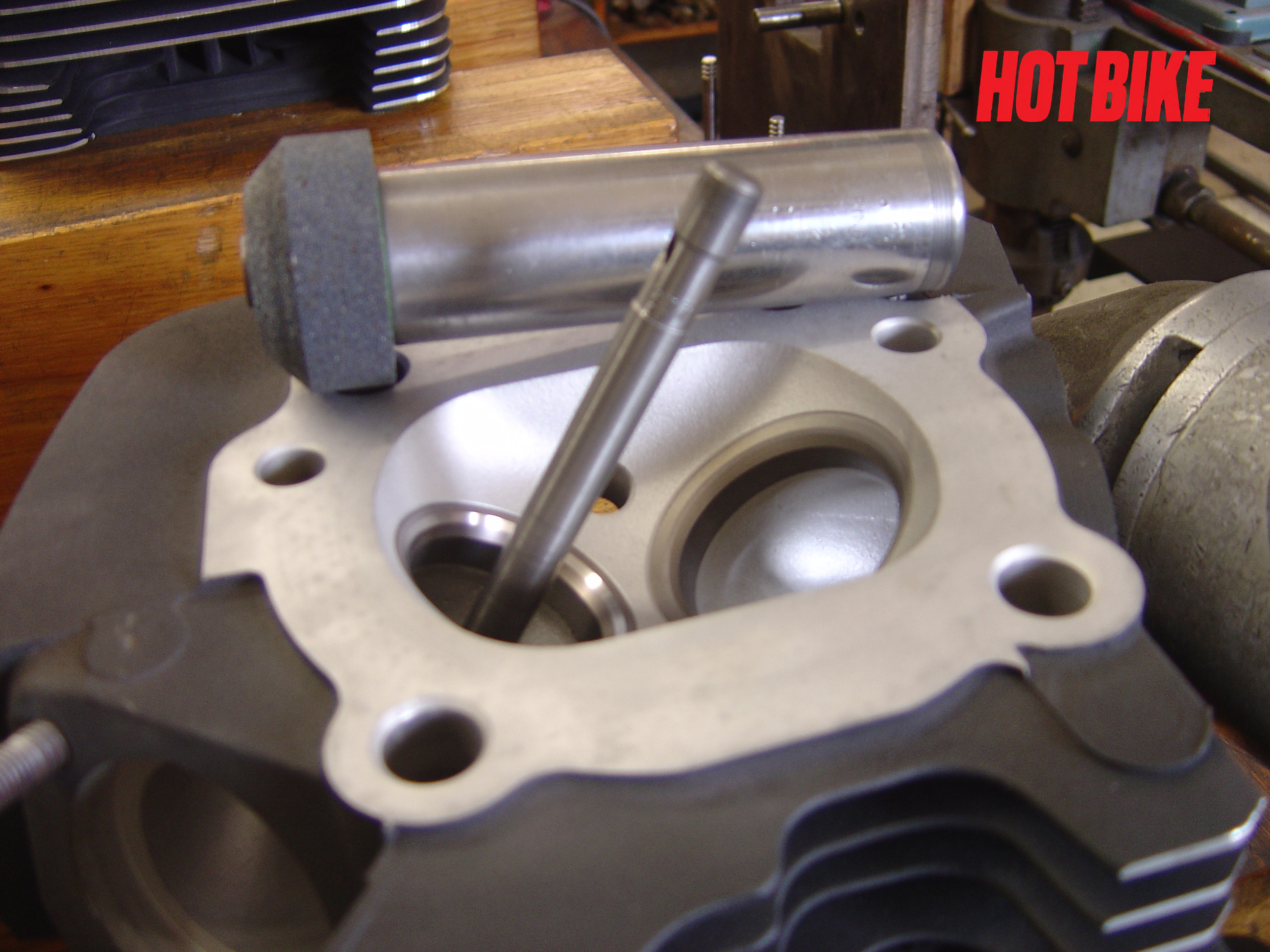
- Once all of the checks have been made, it’s time to grind the valve seats. Stones with a pilot have been used for decades. For a basic valve job it works very well.
Text And Photos: Bob Colvin
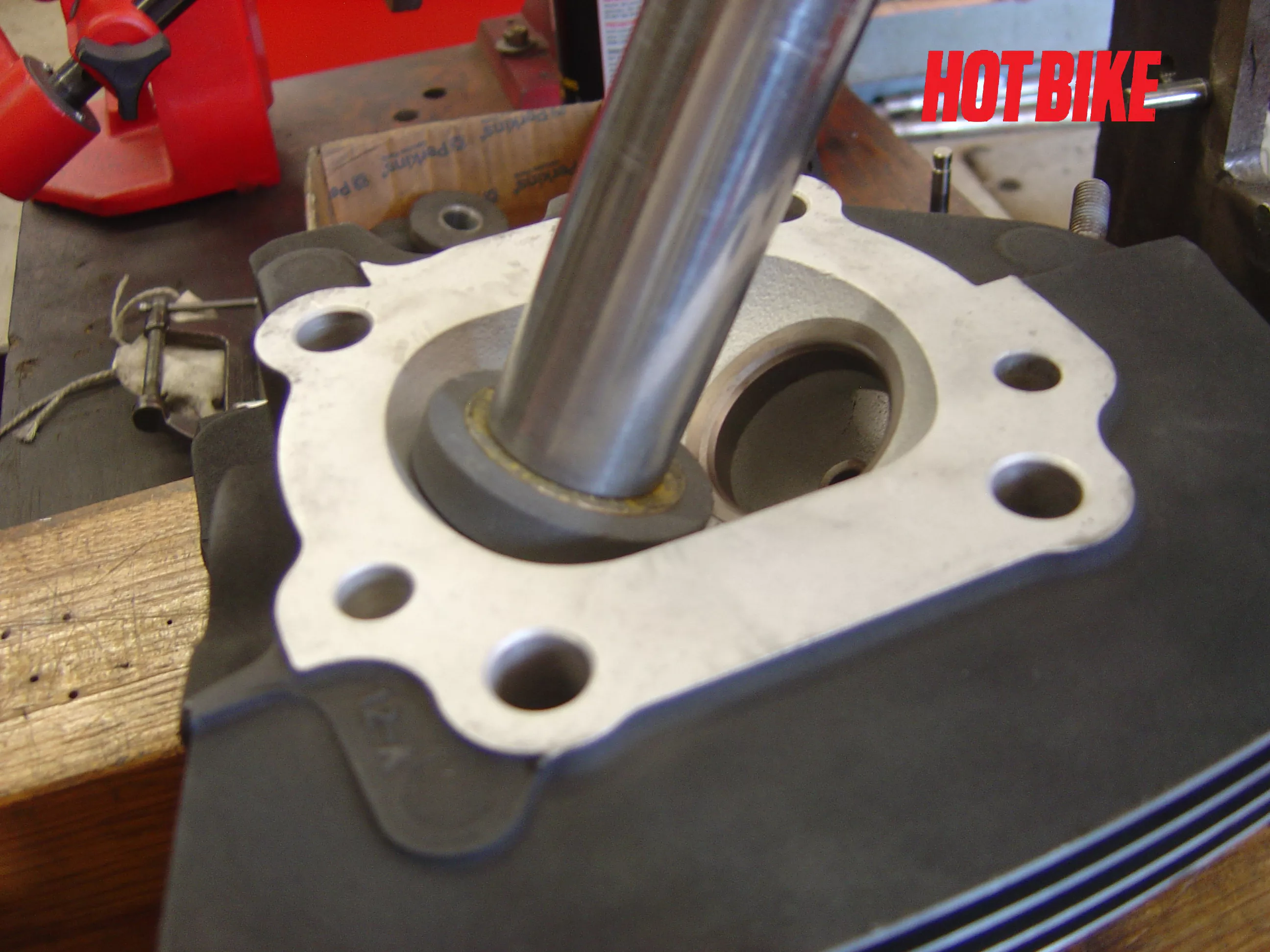
- The stone and driver on the pilot is powered by an electric or air driver.
Text And Photos: Bob Colvin
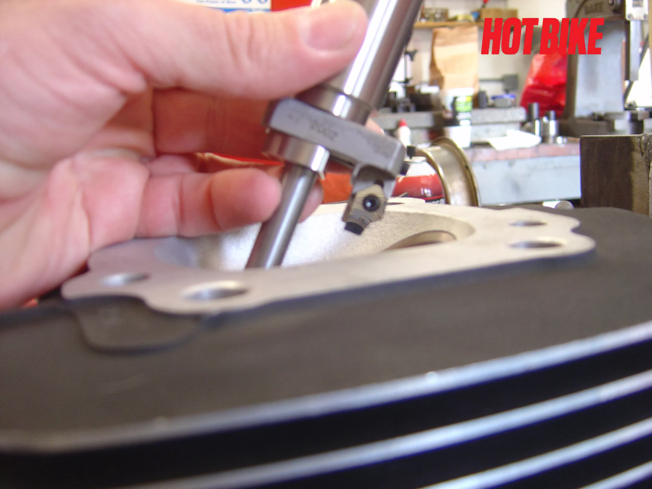
- Next, we used a seat and guide machine. These cut the seats using high-speed steel or carbide cutters. They also cut all the seat angles at one time. Some cutters have up to seven angles for improved flow.
Text And Photos: Bob Colvin
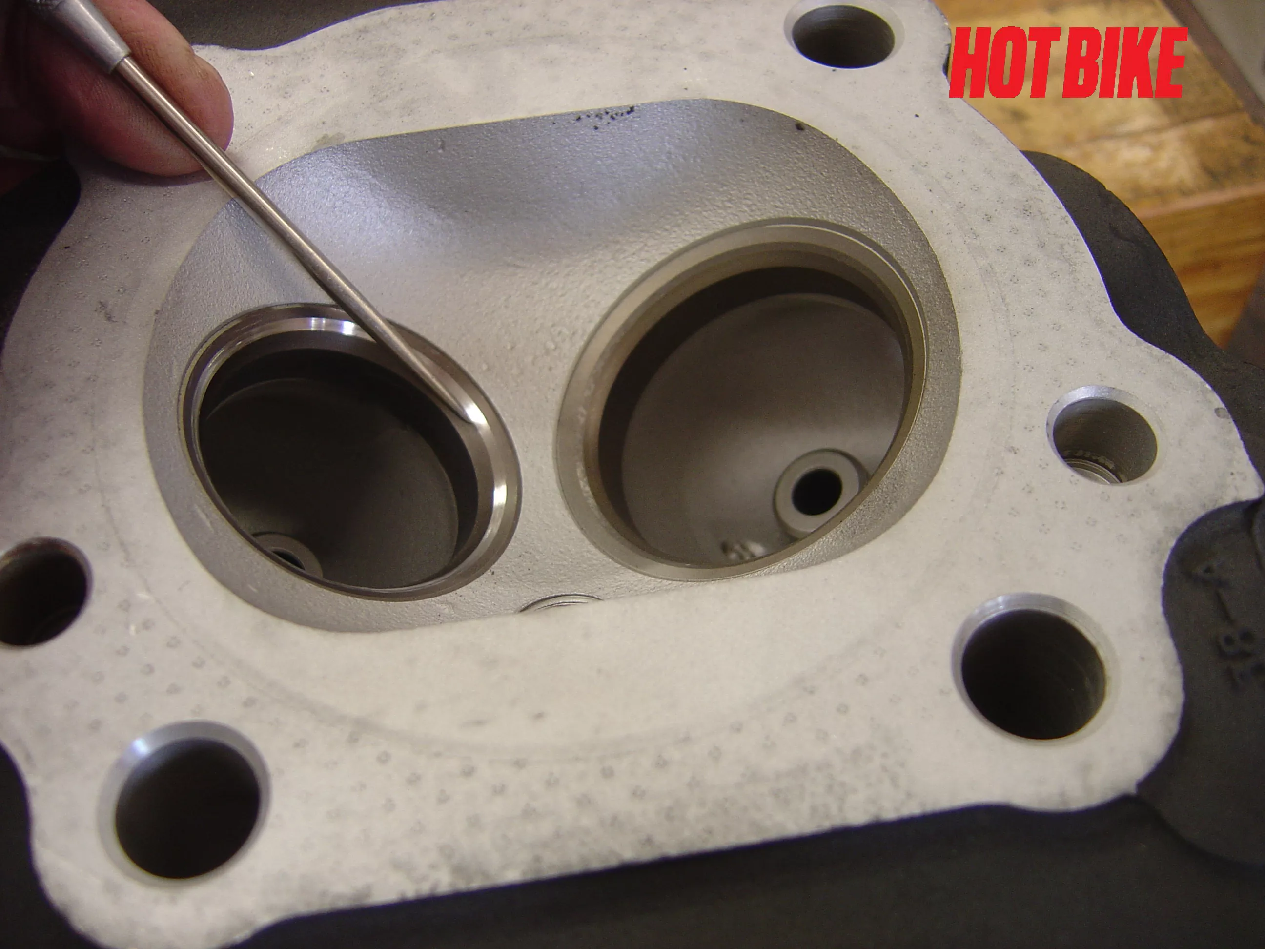
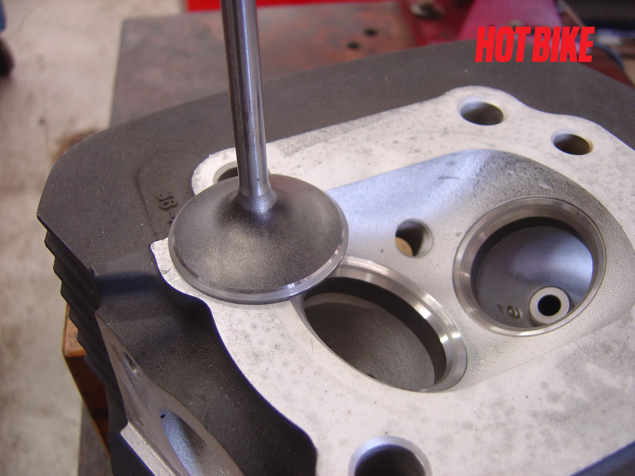
- The first angle is 45 degrees and mates with the valve to create a seal. Notice this exhaust seat cleaned up with the first pass, but the valve was extremely pitted.
Text And Photos: Bob Colvin
- The intakes seats were very pitted, but the intake valves weren’t. With less than 20,000 miles these heads were already in need of a valve job.
Text And Photos: Bob Colvin
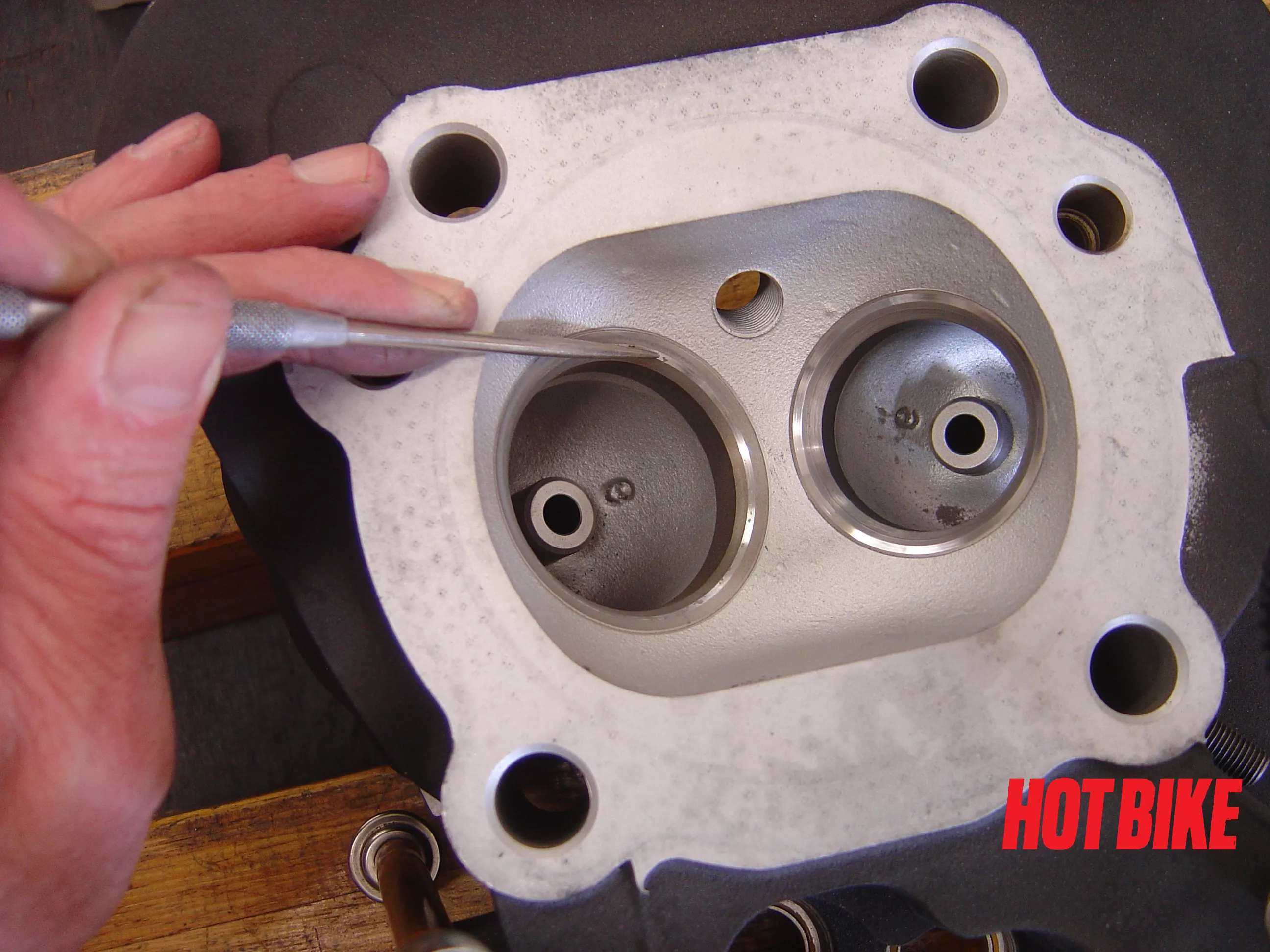
- Here you can see we used a 30-degree angle at the top of the valve seat to square and position the 45 degree.
Text And Photos: Bob Colvin
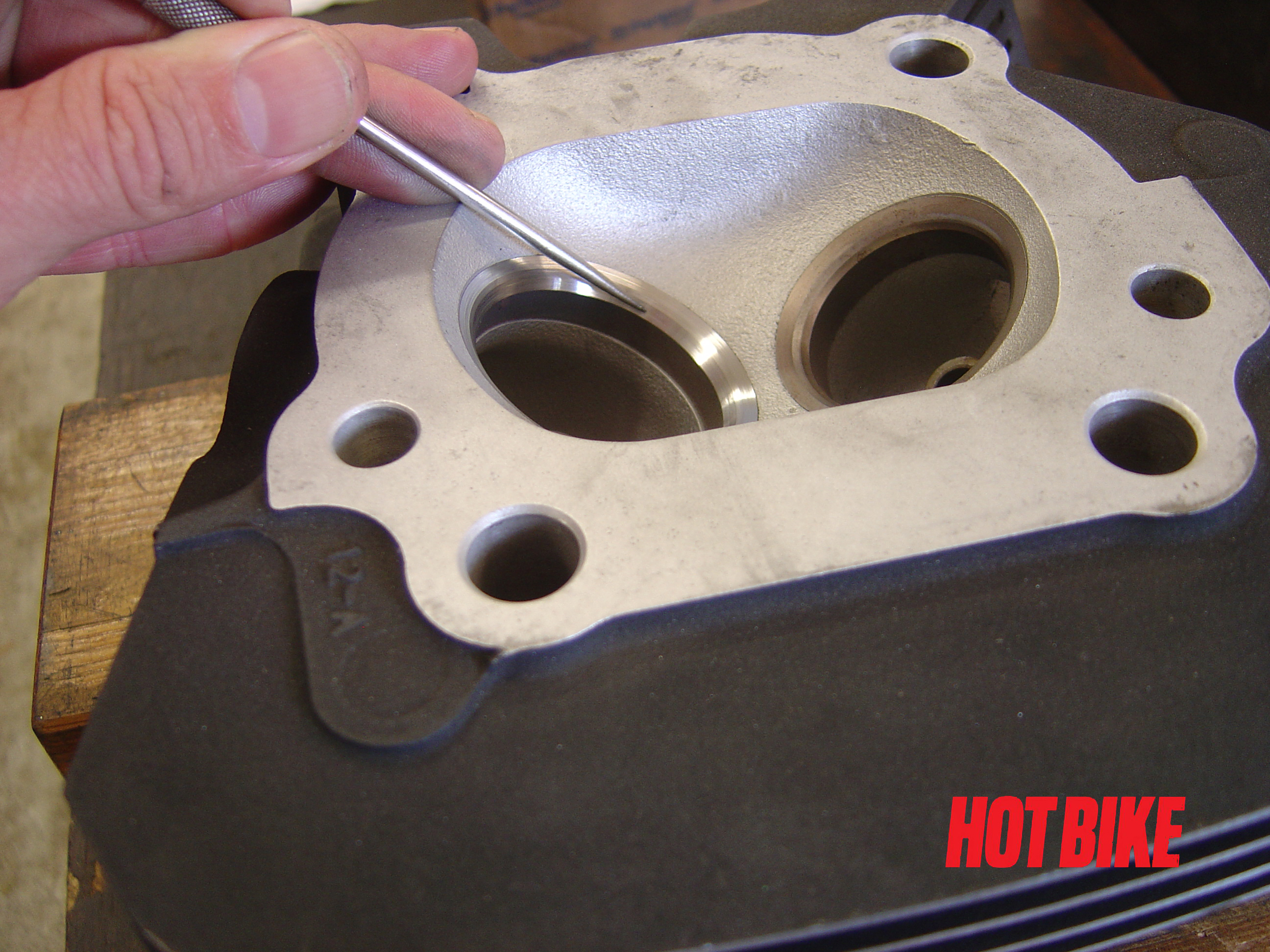
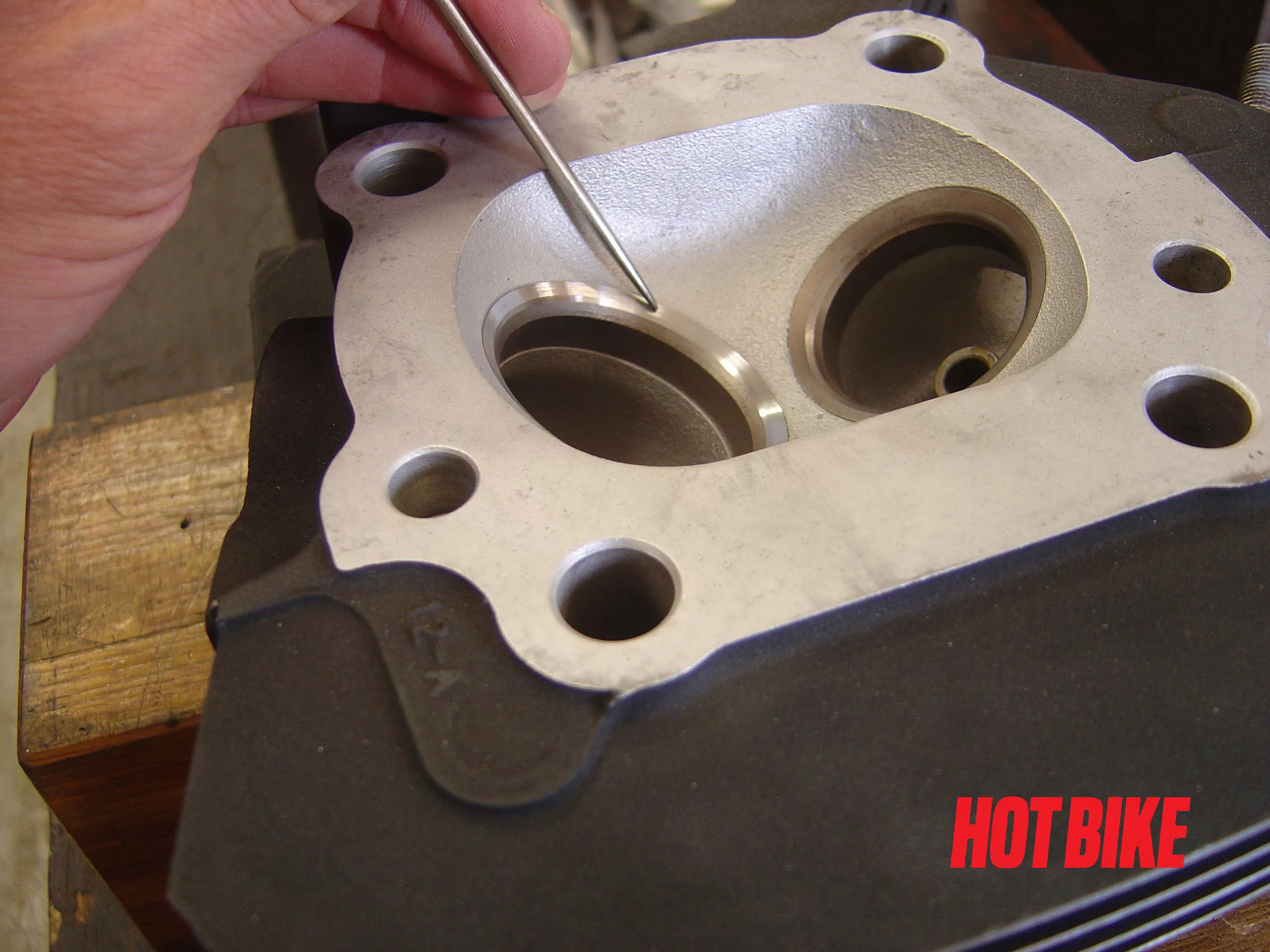
- A 60-degree angle is ground to square and narrow the bottom.
Text And Photos: Bob Colvin
- Once the seats were ground, we used fine grease based lapping compound. The valve is lightly coated with compound. Placed in its guide, the valve is oscillated using a suction cup. This step marries the valve and seat together.
Text And Photos: Bob Colvin
- At this point, parts cannot be interchanged. Notice the mating surface is about 1/3 of the way down the valve face.
Text And Photos: Bob Colvin

- It’s time to clean all of the part for reassemble. Heads go into the sink. Yep, we use hot soapy water and give them a good scrubbing. Valves go into the wash tank and are then cleaned with lacquer thinner.
Text And Photos: Bob Colvin
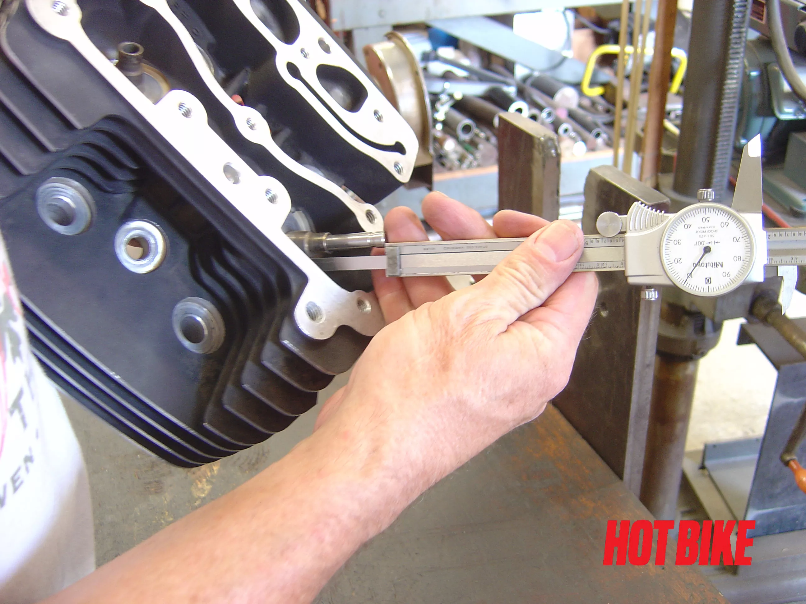
- Once all of the valves have been lapped and everything is cleaned. Valve stem protrusion is checked. Using a dial caliper, measure from the end of the valve stem to the valve spring pad. Factory spec for this year was 2.034 to 2.064. After too many valve jobs, the valves are too deep in the head. This reduces airflow and changes valve geometry with the rocker arm to valve stem interface. These heads were within spec.
Text And Photos: Bob Colvin
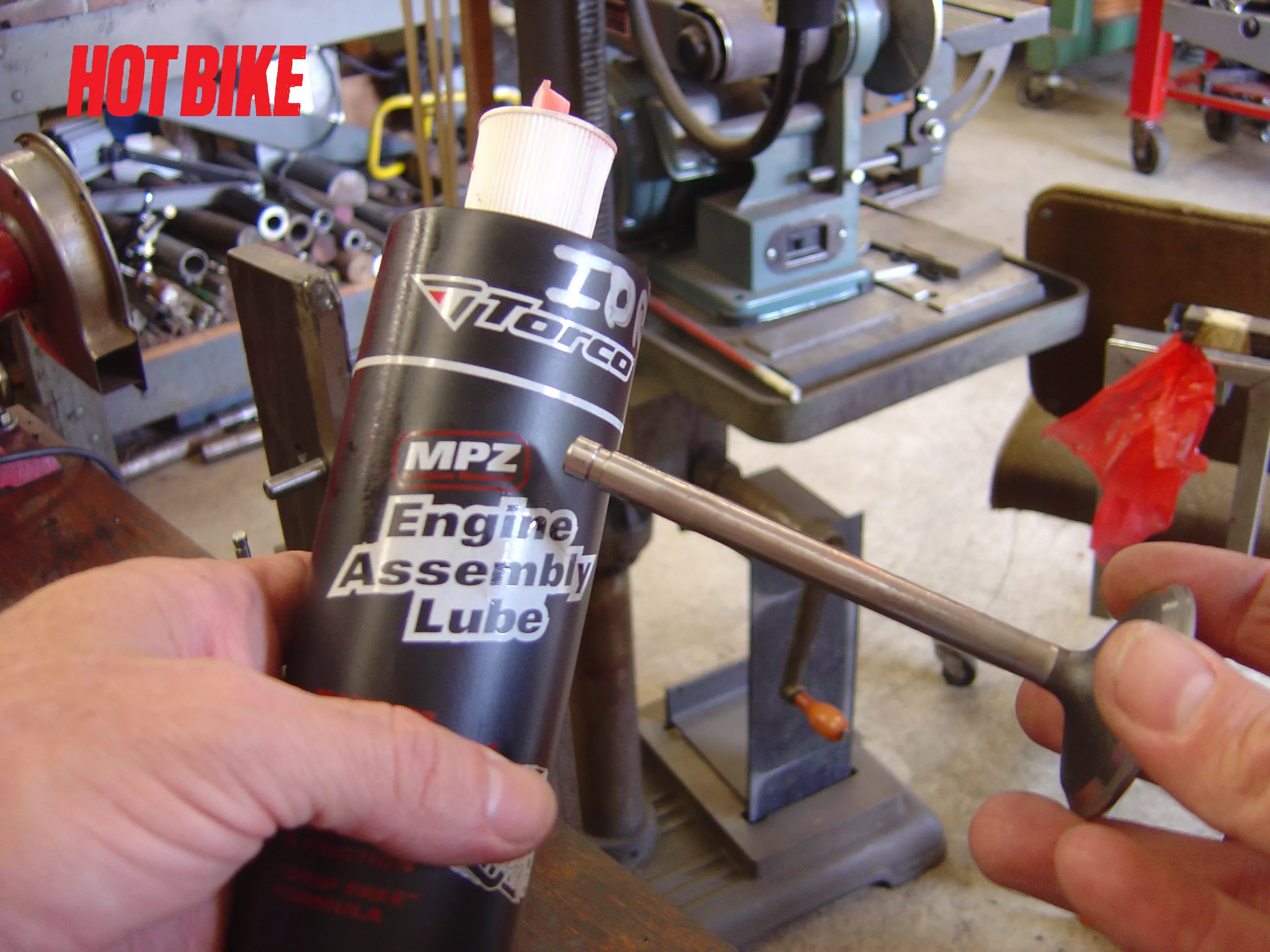
- Lubricate valve stems and guides with assemble lube. After installing new valve seals we used the valve spring compressor to reinstall the valve springs.
Text And Photos: Bob Colvin
- And without further ado, here’s the completed heads ready for installation.
Text And Photos: Bob Colvin
One of our local riders wanted to increase the displacement of his Street Glide. Originally he wanted to bore the cylinders oversize to increase displacement from 96 inches to 103 inches. With less than 20K, we had to convince him to have the heads done to reset the mileage bar on both the cylinders and heads.
Today’s gas sucks. It’s mostly detergents and ethanol. Big Brother has just about removed all of the fuel out of gas. This has caused increased wear in the combustion chamber. Valves and valve seats are showing considerable amounts of wear at much lower mileages.
Follow along as we do a basic valve job on a set of Twin Cam 96-inch heads. In the months to come we’re going to look at high-mileage maintenance work, including valve, valve guide replacement, and resurfacing heads. Along with head setup for high lift cams and installation of compression releases. Enjoy!


